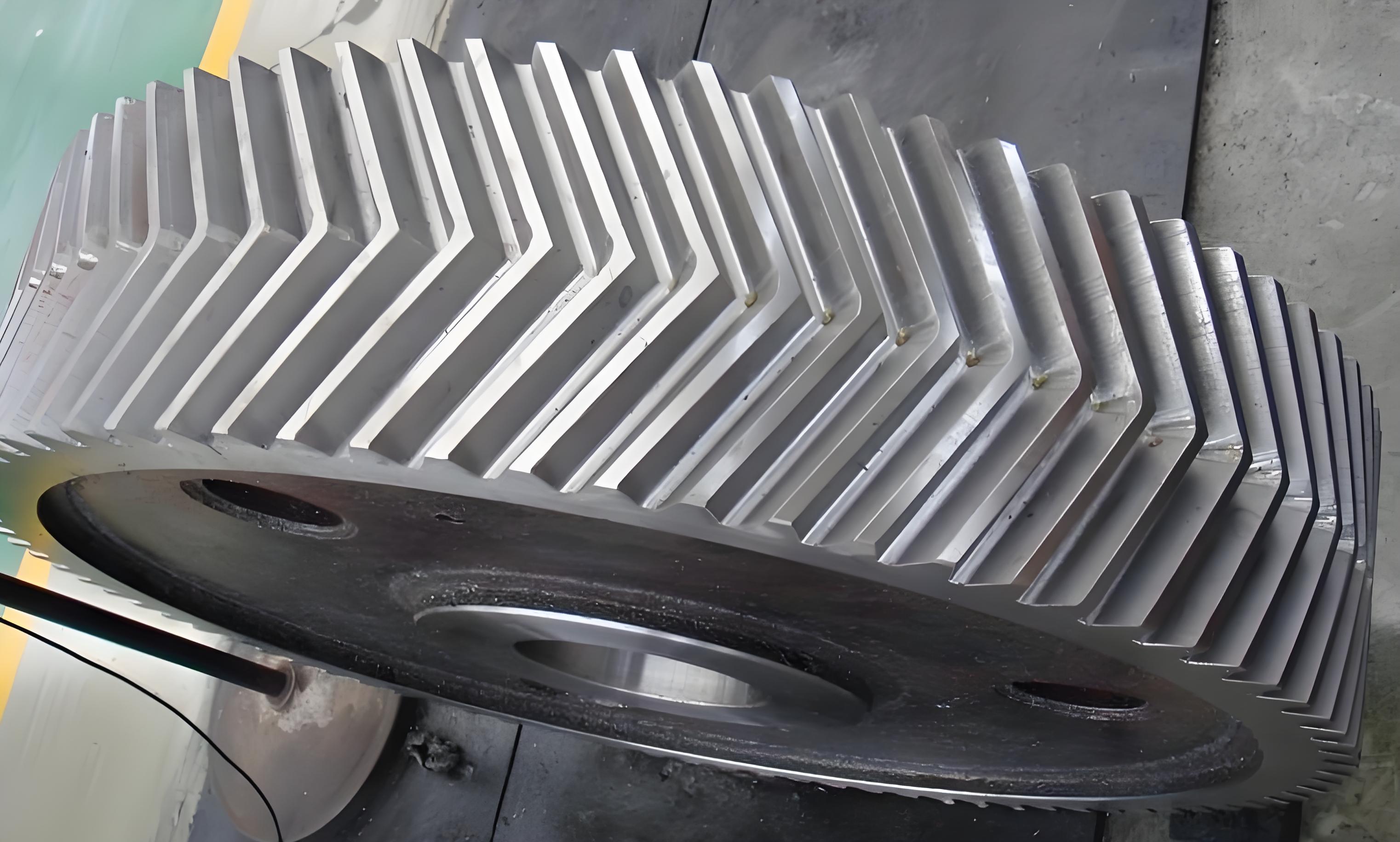
The meshing behavior of a herringbone gear considering lead crowning modification and stagger angle is analyzed in detail. The following content summarizes the key findings and methodologies of the research using tables and illustrations where appropriate.
Abstract
This paper proposes a new axial displacement iteration method for herringbone gear and establishes a Load Transmission Contact Analysis (LTCA) model. The effects of lead crowning modification and tooth surface stagger angle on meshing excitation and load distribution are explored. The results provide insights into improving the meshing stability of herringbone gear.

1. Introduction
Herringbone gear is widely used in high-speed and heavy-load applications due to their advantages in load-bearing capacity and smoothness of operation. However, issues such as meshing stiffness and load distribution can affect their performance. This paper focuses on analyzing the meshing behavior of herringbone gear by considering lead crowning modification and tooth surface stagger angle.
2. Methodology
2.1 LTCA Model Establishment
A new axial displacement iteration method is proposed, and an LTCA model for herringbone gear is established based on the finite element method and the finite line contact theory. The model considers the differences in helix angles at different meshing points and uses Newton’s iteration method to calculate the axial displacement of the driving gear.
2.2 Parameters Considered
- Lead Crowning Modification: The amount of modification varies from 2 μm to 15 μm.
- Tooth Surface Stagger Angle: The stagger angle ranges from 0 to π/N, where N is the number of teeth.
3. Results and Discussion
3.1 Axial Displacement Iteration Method
A comparison of the axial displacement and axial force difference calculated using the traditional iteration method and Newton’s iteration method is shown in Table 1.
Table 1: Comparison of Axial Displacement and Calculation Time
| Symmetry Error (μm) | Average Axial Displacement (μm) – Newton | Average Axial Displacement (μm) – Traditional | Calculation Time (s) – Newton | Calculation Time (s) – Traditional |
|---|---|---|---|---|
| 1 | 1.20 | 1.20 | 0.50 | 1.50 |
| 5 | 6.20 | 6.20 | 0.78 | 2.30 |
| 10 | 12.30 | 12.33 | 0.75 | 3.10 |
The results indicate that Newton’s iteration method is more efficient and applicable to herringbone gear LTCA models with large errors, such as those with tooth surface stagger angles.
3.2 Effects of Lead Crowning Modification
Table 2: Effects of Lead Crowning Modification on Meshing Stiffness and Meshing Error
| C_max (μm) | Mean Meshing Stiffness k_m (kN·mm⁻¹) | Amplitude of k_m (kN·mm⁻¹) | Mean Meshing Error e_m (μm) | Amplitude of e_m (μm) |
|---|---|---|---|---|
| 2 | 1622.15 | 282.67 | 1.61 | 1.94 |
| 4 | 1403.73 | 203.43 | 2.09 | 2.15 |
| 6 | 1263.28 | 303.84 | 2.18 | 2.27 |
| 8 | 1170.47 | 431.09 | 2.20 | 2.34 |
| 10 | 1104.83 | 422.13 | 2.22 | 2.45 |
| 15 | 1004.10 | 426.93 | 2.25 | 2.55 |
The increase in lead crowning modification reduces the mean meshing stiffness and increases the mean and amplitude of meshing errors. The load distribution on the tooth surface becomes more concentrated towards the middle as C_max increases.
3.3 Effects of Tooth Surface Stagger Angle
The results show that as the stagger angle increases, the mean axial displacement increases, and the fluctuations become more severe. The periodic axial movement of the herringbone gear during meshing is due to the time-varying axial force difference.
4. Conclusion
This paper presents a comprehensive analysis of the meshing behavior of herringbone gear considering lead crowning modification and tooth surface stagger angle. The proposed axial displacement iteration method is efficient and applicable to models with large errors. The results indicate that lead crowning modification affects the meshing stiffness, meshing error, and load distribution, while the tooth surface stagger angle influences the axial displacement and axial force balance. These findings provide valuable insights for improving the meshing stability of herringbone gear.
