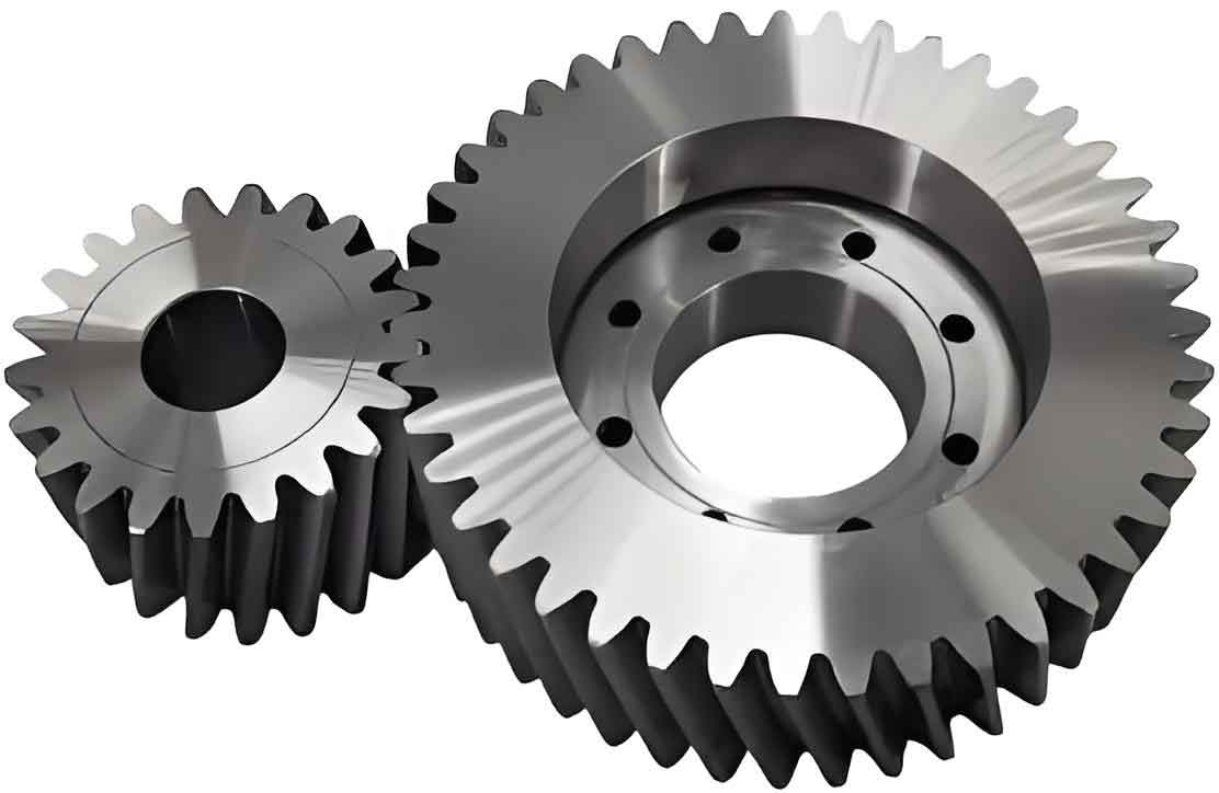
This study investigates the meshing performance compensation mechanism for cylindrical gears operating under variable center distance conditions (184-186.93 mm) in high-speed rolling mills. A finite element model considering 61.36 μm meshing misalignment was established to analyze five typical center distance configurations.
1. Fundamental Meshing Characteristics
The meshing parameters of cylindrical gears follow these fundamental relationships:
$$ε_α = \frac{1}{2π}\left[z_1(\tanα_{at1} – \tanα_t’) + z_2(\tanα_{at2} – \tanα_t’)\right]$$
$$ε_β = \frac{B\sinβ}{πm_n}$$
$$ε_γ = ε_α + ε_β$$
Where \(ε_α\), \(ε_β\), and \(ε_γ\) represent transverse, axial, and total contact ratios respectively. Table 1 shows the geometric parameters of the cylindrical gear pair.
| Parameter | Pinion | Gear |
|---|---|---|
| Teeth | 33 | 37 |
| Module (mm) | 5 | 5 |
| Pressure Angle (°) | 20 | 20 |
| Helix Angle (°) | 18 | 18 |
| Face Width (mm) | 132 | 132 |
| Center Distance (mm) | 184-186.93 | |

2. Meshing Performance Analysis
The contact ratio decreases linearly with increasing center distance:
$$Δε_γ = 0.5 \quad (184 \text{ mm} \rightarrow 186.93 \text{ mm})$$
Contact pattern analysis reveals significant edge-loading effects:
| Center Distance (mm) | Contact Area (%) | Stress Concentration Factor |
|---|---|---|
| 184.00 | 78.4 | 1.31 |
| 186.93 | 68.9 | 1.87 |
The bending stress distribution follows:
$$σ_b = \frac{F_t}{bm_n}\left(\frac{6h_f}{\cosα_n} – \frac{s_f^2}{2m_n}\right)Y_β$$
Where \(Y_β\) represents the helix angle factor. Maximum contact stress exceeds 1,970 MPa at 186.93 mm center distance, demonstrating the critical need for modification.
3. Optimization Strategy for Cylindrical Gears
The proposed multi-axis modification combines:
- Helix angle correction
- Crowning modification
- Tip relief
The modification profile is defined as:
$$Δ_{total} = Δ_{helix} + Δ_{crown} + Δ_{tip}$$
$$Δ_{crown}(x) = C_β\left[1 – \left(\frac{2x}{B}\right)^2\right]$$
$$Δ_{tip}(r) = Δ_{Qt}\left(\frac{r – P_1}{P_2 – P_1}\right)^2$$
| Parameter | Pinion | Gear |
|---|---|---|
| Helix Correction (μm) | 0 | 60 |
| Crowning (μm) | 0 | 35 |
| Tip Relief (μm) | 60 | 55 |
4. Performance Validation
The optimized cylindrical gears demonstrate significant improvement:
| Parameter | Original | Modified |
|---|---|---|
| Max Contact Stress (MPa) | 1,970 | 953 |
| Bending Stress Reduction (%) | – | 18.6 |
| TE Peak-Peak (μm) | 24.3 | 9.8 |
The transmission error improvement follows:
$$TE_{reduction} = \frac{1}{N}\sum_{i=1}^{N}\left(\frac{TE_{original} – TE_{modified}}{TE_{original}}\right) \times 100\% = 59.7\%$$
5. Conclusion
This study establishes a comprehensive modification strategy for cylindrical gears operating under variable center distance conditions. The combined helix correction, crowning, and tip relief modifications effectively:
- Reduce maximum contact stress by 51.6%
- Improve load distribution uniformity
- Enhance center distance adaptability
- Decrease transmission error by 59.7%
The proposed methodology provides theoretical guidance for optimizing cylindrical gear performance in variable center distance applications, particularly in high-speed rolling mill transmissions.
