
I have spent considerable effort investigating the meshing behavior of hypoid bevel gears produced by the face-hobbing method. A hypoid bevel gear pair is widely used in automotive axles, helicopter transmissions, and industrial reducers because it combines high load capacity, large overlap ratio, and tolerance to assembly misalignment. Among the available manufacturing routes, face hobbing has become increasingly attractive for mass production since it enables continuous indexing, simultaneous cutting of both flanks, and short cycle times. Nevertheless, the tooth surface of a face-hobbed hypoid bevel gear is generated by a complex coupled motion of the cutter head and the machine tool. As a result, the geometric deviation caused by tool errors, machine settings, and assembly misalignment directly affects the contact pattern, transmission error, and root stress. In this work I develop a precise mathematical model of a face-hobbed hypoid bevel gear, establish a loaded contact analysis model, and study the influence of tool errors and misalignment on meshing characteristics.
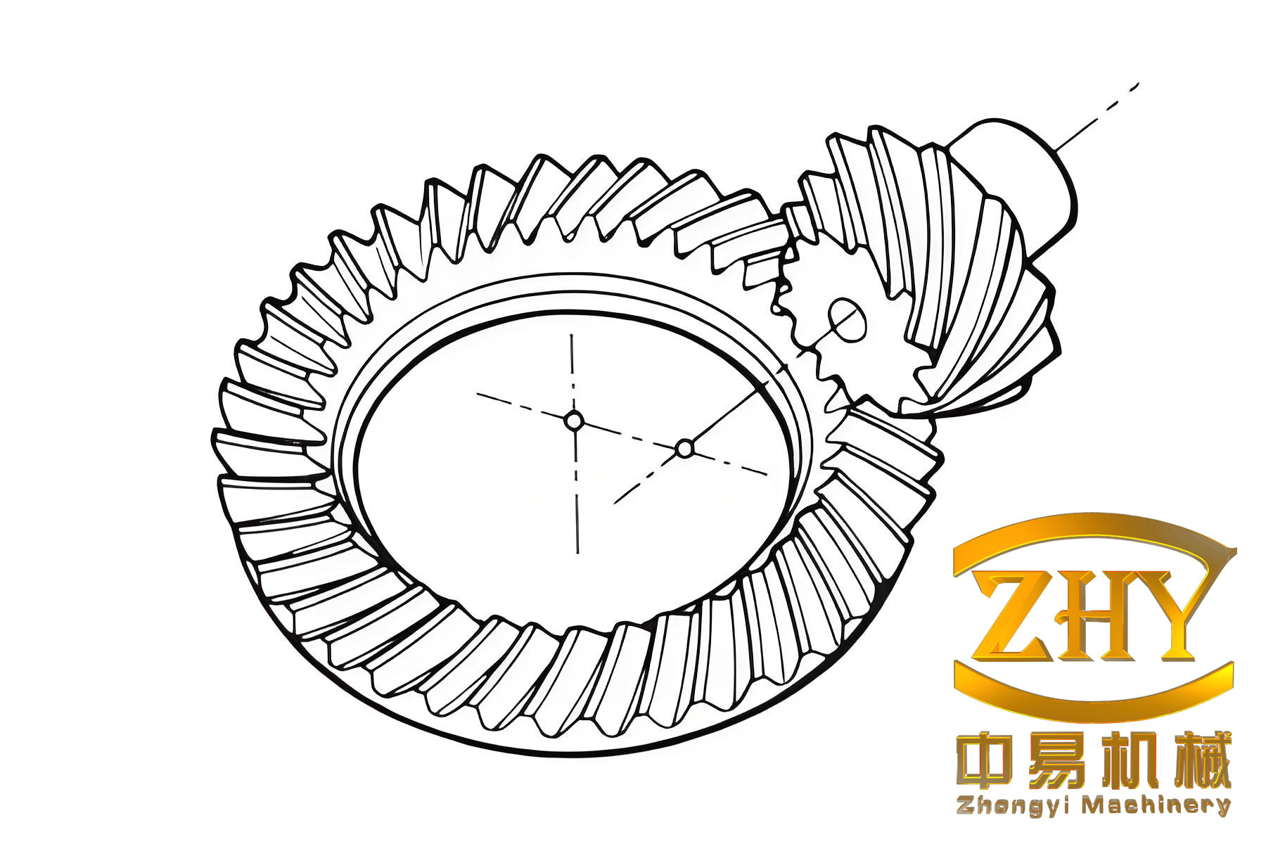
The hypoid bevel gear is different from a spiral bevel gear because its pitch surfaces are hyperboloids of revolution rather than cones. This offset between the pinion axis and the gear axis allows a larger pinion diameter, greater stiffness, and more favorable load distribution. However, the same offset makes the tooth surface geometry highly sensitive to manufacturing and assembly errors. In my analysis I treat the hypoid bevel gear as a three-dimensional conjugate problem in which the cutter blade, cutter head, machine tool, and work blank form a closed kinematic chain. The mathematical formulation that I use is based on the neutral data (ND) normal reference of the cutting tool, which provides a consistent way to describe blade profile, rake angle, relief angle, and regrinding angle.
I begin by reviewing the face-hobbing principle. In face hobbing, the cutter head rotates about its own axis while the cradle rotates about the machine axis. The blades are arranged in groups. Each group contains at least one inner blade and one outer blade. The inner blade cuts the convex flank, and the outer blade cuts the concave flank. Because the cutter head and the work blank rotate in a timed relationship, the tooth slots are cut continuously. The resulting tooth trace is an extended epicycloid. The generating surface is the envelope of the blade trajectories. For a Formate gear, the generating surface is identical to the blade trajectory surface. For a generating pinion, the tooth surface is the envelope of the family of cutter surfaces.
The machine tool kinematics can be described by a series of coordinate transformations. I define the blade edge in the ND normal reference frame, then transform it to the cutter head frame, then to the cradle frame, and finally to the work blank frame. The general form of the transformation is:
$$ \mathbf{r}_w(u,\theta,\phi) = \mathbf{M}_{w,c}(\phi) \, \mathbf{M}_{c,h} \, \mathbf{M}_{h,b}(\theta) \, \mathbf{r}_b(u) $$
where \( \mathbf{r}_b(u) \) is the blade edge position in the blade frame, \( \mathbf{M}_{h,b} \) is the blade-to-cutter-head transformation, \( \mathbf{M}_{c,h} \) is the cutter-head-to-cradle transformation, and \( \mathbf{M}_{w,c} \) is the cradle-to-work transformation. The parameter \( u \) is the distance along the main cutting edge, \( \theta \) is the cutter head rotation angle, and \( \phi \) is the cradle rotation angle.
For the Formate gear, the tooth surface is obtained directly from the cutter trajectory. For the generating pinion, the tooth surface must satisfy the meshing equation:
$$ \mathbf{n} \cdot \mathbf{v}^{(12)} = 0 $$
where \( \mathbf{n} \) is the unit normal to the cutter surface and \( \mathbf{v}^{(12)} \) is the relative velocity between the cutter and the work blank. The meshing equation is solved for the cradle rotation angle \( \phi \), which is then substituted back into the transformation to obtain the final tooth surface coordinates.
The blade geometry is critical because the main cutting edge forms the working tooth profile. I use a three-face blade with a circular main cutting edge and a tip fillet. The main cutting edge is defined in the ND normal reference plane. The blade profile can be written as:
$$ \mathbf{r}_b(u) = \begin{bmatrix} R_s \sin(u/R_s) \\ R_s \cos(u/R_s) – R_s \\ 0 \end{bmatrix} $$
where \( R_s \) is the radius of the main cutting edge. The tip fillet is defined by another circular arc that is tangent to the main cutting edge at the transition point. The complete blade edge is therefore a piecewise curve composed of the main cutting edge and the tip fillet.
I now summarize the key parameters of the hypoid bevel gear pair and the cutter head that I used in my investigation. The gear pair has 11 pinion teeth and 47 gear teeth. The offset is 38.1 mm, and the shaft angle is 90 degrees. The pinion is left-handed and the gear is right-handed. The cutter head has a nominal radius of 76 mm. The blade pressure angles, rake angles, relief angles, and regrinding angles are different for the convex and concave flanks. The machine settings include tilt angle, swivel angle, radial distance, initial cradle angle, vertical offset, sliding base, horizontal setting, machine root angle, and roll ratio. The pinion is generated, while the gear is Formate. The roll ratio for the pinion is 4.722168, and the gear is cut without generating motion.
| Parameter | Pinion concave | Pinion convex | Gear concave | Gear convex |
|---|---|---|---|---|
| Number of teeth | 11 | 11 | 47 | 47 |
| Hand of spiral | Left | Left | Right | Right |
| Reference radius (mm) | 76 | 76 | 76 | 76 |
| Cutting edge radius (mm) | 1093.65 | 1062.73 | 1360.74 | 1276.45 |
| Profile pressure angle (deg) | 22.3059 | 20.1933 | 18.9931 | 23.5060 |
| Regrinding angle (deg) | 4.3674 | 4.7856 | 5.0309 | 4.1101 |
| Side relief angle (deg) | 13.3885 | 12.6729 | 13.3823 | 12.6781 |
| Rake angle (deg) | 9.5870 | 10.3059 | 12.6781 | 9.6107 |
| Machine setting | Symbol | Pinion | Gear |
|---|---|---|---|
| Tilt angle (deg) | i | 3.3325 | 0 |
| Swivel angle (deg) | j | 146.9405 | 0 |
| Radial distance (mm) | S_R | 121.9391 | 122.009 |
| Initial cradle angle (deg) | q | 52.6673 | -29.7048 |
| Vertical offset (mm) | E | 39.8352 | 0 |
| Sliding base (mm) | B | -12.2486 | 0 |
| Horizontal setting (mm) | A | 3.1158 | 13.9199 |
| Machine root angle (deg) | gamma | 23.4453 | 64.7995 |
| Roll ratio | i_gp | 4.722168 | 0 |
Using the mathematical model described above, I generated the tooth surface point sets for both the pinion and the gear. The point sets were imported into a three-dimensional modeling environment to create the solid models. I then assembled the pinion and gear according to the mounting distance and offset. The assembly showed no interference at the toe or heel, which provided an initial indication that the mathematical model and the modeling procedure were correct.
After establishing the nominal tooth surface model, I introduced tool errors to study their influence on tooth surface geometry. The tool errors that I considered are the main cutting edge radius error \( \Delta R_s \), the reference pressure angle error \( \Delta \alpha_0 \), the rake angle error \( \Delta \gamma \), the regrinding angle error \( \Delta \varepsilon \), and the side relief angle error \( \Delta \delta \). These errors are defined in the ND normal reference frame. The positive and negative directions are defined with respect to the standard tooth surface. A positive deviation means that the actual tooth surface lies outside the standard surface, while a negative deviation means that the actual tooth surface lies inside the standard surface.
The tooth surface deviation is computed as the normal distance between the actual surface and the standard surface. I discretized the tooth surface into a grid along the profile direction and the lengthwise direction. For each grid point I computed the deviation. The maximum deviation, minimum deviation, and the location of these extremes were recorded. I also examined the deviation at the top, root, toe, and heel regions.
The first tool error that I investigated is the main cutting edge radius error. I varied the cutting edge radius by -100 mm, -50 mm, +50 mm, and +100 mm with respect to the nominal value. The results show that the tooth surface deviation is negative when the cutting edge radius is reduced and positive when the cutting edge radius is increased. The deviation is larger at the heel than at the toe. The maximum deviation occurs near the top of the heel, and the minimum deviation occurs near the middle of the toe. The difference between the maximum and minimum deviation is relatively small compared with other tool errors. Therefore, the main cutting edge radius has a limited influence on the overall tooth surface geometry of the hypoid bevel gear.
| Cutting edge radius error (mm) | Maximum deviation (mm) | Minimum deviation (mm) |
|---|---|---|
| -100 | -0.023 | -0.015 |
| -50 | -0.012 | -0.008 |
| +50 | 0.015 | 0.010 |
| +100 | 0.023 | 0.015 |
The second tool error is the reference pressure angle error. I varied the pressure angle by -1 degree, -0.5 degree, +0.5 degree, and +1 degree. The pressure angle error has a very strong influence on the tooth surface geometry. When the pressure angle is increased, the tooth surface deviation becomes negative. When the pressure angle is decreased, the deviation becomes positive. The maximum deviation is located near the top of the heel, and the minimum deviation is located near the middle of the toe. The deviation increases almost linearly with the pressure angle error. For a pressure angle error of +1 degree, the maximum deviation reaches 0.2303 mm. For a pressure angle error of -1 degree, the maximum deviation reaches 0.1159 mm. The positive pressure angle error produces a larger deviation than the negative pressure angle error.
| Pressure angle error (deg) | Maximum deviation (mm) | Minimum deviation (mm) |
|---|---|---|
| -1.0 | 0.1159 | 0.0043 |
| -0.5 | 0.0572 | 0.0025 |
| +0.5 | 0.1144 | 0.0046 |
| +1.0 | 0.2303 | 0.0025 |
The third tool error is the regrinding angle error. I varied the regrinding angle by -1 degree, -0.5 degree, +0.5 degree, and +1 degree. The regrinding angle error produces a deviation pattern similar to that of the pressure angle error, but the magnitude is much smaller. The maximum deviation is located near the top of the heel, and the minimum deviation is located near the middle of the heel. For a regrinding angle error of +1 degree, the maximum deviation is 0.0312 mm. For a regrinding angle error of -1 degree, the maximum deviation is 0.0158 mm. The deviation increases with the absolute value of the regrinding angle error.
| Regrinding angle error (deg) | Maximum deviation (mm) | Minimum deviation (mm) |
|---|---|---|
| -1.0 | 0.0158 | 0.00065 |
| -0.5 | 0.0154 | 0.00066 |
| +0.5 | 0.0157 | 0.00066 |
| +1.0 | 0.0312 | 0.00065 |
The fourth tool error is the rake angle error. I varied the rake angle by -1 degree, -0.5 degree, +0.5 degree, and +1 degree. The rake angle error has a very small influence on the tooth surface geometry. The maximum deviation is on the order of \( 10^{-6} \) mm, which is negligible compared with the other errors. The deviation pattern is similar to that of the pressure angle error, but the magnitude is extremely small. Therefore, the rake angle error mainly affects the cutting condition and surface finish rather than the macroscopic tooth surface geometry of the hypoid bevel gear.
| Rake angle error (deg) | Maximum deviation (mm) | Minimum deviation (mm) |
|---|---|---|
| -1.0 | \( 4.9 \times 10^{-6} \) | \( 2.2 \times 10^{-6} \) |
| -0.5 | \( 1.3 \times 10^{-6} \) | \( 3.5 \times 10^{-9} \) |
| +0.5 | \( 7.2 \times 10^{-6} \) | \( 1.1 \times 10^{-8} \) |
| +1.0 | \( 1.8 \times 10^{-6} \) | \( 3.0 \times 10^{-9} \) |
The fifth tool error is the side relief angle error. I varied the side relief angle by -1 degree, -0.5 degree, +0.5 degree, and +1 degree. The side relief angle error produces a deviation pattern similar to that of the pressure angle and regrinding angle errors. The maximum deviation is located near the top of the heel, and the minimum deviation is located near the middle of the toe. For a side relief angle error of +1 degree, the maximum deviation is 0.0029 mm. For a side relief angle error of -1 degree, the maximum deviation is 0.0027 mm. The deviation increases with the absolute value of the side relief angle error.
| Side relief angle error (deg) | Maximum deviation (mm) | Minimum deviation (mm) |
|---|---|---|
| -1.0 | 0.0027 | 0.00013 |
| -0.5 | 0.0025 | 0.00012 |
| +0.5 | 0.0023 | 0.00011 |
| +1.0 | 0.0029 | 0.00013 |
Comparing the five tool errors, I find that the reference pressure angle has the strongest influence on the tooth surface geometry of the hypoid bevel gear. The side relief angle and the regrinding angle have moderate influence. The rake angle has the weakest influence. The main cutting edge radius has a small influence. The maximum deviation is consistently located near the top of the heel, while the minimum deviation is located near the middle of the toe. The deviation at the top and root is generally larger than the deviation at the middle of the tooth. This means that tool errors can significantly change the contact pattern and the transmission error of the hypoid bevel gear.
After analyzing the tooth surface geometry, I built a finite element model for loaded contact analysis. The model includes the pinion and the gear. The pinion is modeled with all teeth, while the gear is modeled with a sector of 11 teeth to reduce computational cost. The material is assumed to be homogeneous hardened steel with a Young’s modulus of 210 GPa and a Poisson’s ratio of 0.3. The contact between the pinion concave flank and the gear convex flank is defined as a surface-to-surface contact with a hard contact pressure-overclosure relationship and a frictionless tangential behavior. The pinion is driven by a reference point coupled to its inner surface. The gear is loaded by a torque applied to a reference point coupled to its inner surface. The analysis is performed in three steps. In the first step, the pinion is rotated by a small angle to establish contact. In the second step, the torque is applied to the gear. In the third step, the pinion is rotated further to simulate the meshing process.
The finite element mesh consists of approximately 17,600 elements for the pinion and 89,400 elements for the gear. The pinion uses tetrahedral elements, and the gear uses hexahedral elements. The mesh is refined near the contact zone to capture the contact pressure and root stress accurately. The contact pattern, transmission error, and root bending stress are extracted from the finite element results.
In addition to the finite element model, I built a complete axle system model using a commercial multibody dynamics software. The axle system includes the input shaft, the hypoid bevel gear pair, the differential, the output half shafts, the hubs, the bearings, and the housing. The power flow is from the input shaft to the pinion, then to the gear, then to the differential case, then to the differential side gears, then to the output half shafts, and finally to the hubs. The bearings are modeled with their actual stiffness and location. The housing is imported from a finite element model and connected to the bearing reference points.
The axle system model is used to calculate the misalignment of the hypoid bevel gear pair under different load cases. The misalignment is described by four components: the offset error \( \Delta E \), the pinion axial displacement \( \Delta X_P \), the gear axial displacement \( \Delta X_W \), and the shaft angle error \( \Delta \Sigma \). The offset error is defined as the change in the distance between the pinion axis and the gear axis. The pinion axial displacement is defined as the displacement of the pinion along its own axis. The gear axial displacement is defined as the displacement of the gear along its own axis. The shaft angle error is defined as the change in the angle between the pinion axis and the gear axis. I considered three load cases: a low-torque high-speed case with 50 Nm at 6000 rpm, a medium-torque case with 450 Nm at 680 rpm, and a high-torque case with 900 Nm at 330 rpm.
| Load case | Input speed (rpm) | Input torque (Nm) | Duration (hr) |
|---|---|---|---|
| Case 1 | 6000 | 50 | 100 |
| Case 2 | 680 | 450 | 100 |
| Case 3 | 330 | 900 | 100 |
The theoretical misalignment is calculated without considering any manufacturing or assembly errors. The results show that the misalignment increases with the load. The pinion axial displacement and the offset error are the dominant components. The gear axial displacement is relatively small. The shaft angle error also increases with the load. For the high-torque case, the total offset error reaches 132.4 micrometers, and the total pinion axial displacement reaches 199.1 micrometers. The total gear axial displacement reaches 113.7 micrometers, and the total shaft angle error reaches -0.8006 degrees. The misalignment of the pinion is larger than that of the gear, which means that the pinion support stiffness has a significant effect on the meshing behavior of the hypoid bevel gear.
| Component | Case 1 (50 Nm) | Case 2 (450 Nm) | Case 3 (900 Nm) |
|---|---|---|---|
| Offset error E (µm) | 13.39 | 74.60 | 132.40 |
| Pinion axial displacement X_P (µm) | -12.44 | -65.00 | -113.04 |
| Gear axial displacement X_W (µm) | 21.11 | 113.65 | 199.10 |
| Shaft angle error Σ (deg) | -0.0586 | -0.4235 | -0.8006 |
I then introduced a preset eccentricity of the housing to compensate for the misalignment. The preset eccentricity means that the output half shaft axis is intentionally offset from the housing axis before loading. This is a common practice in axle manufacturing to reduce the misalignment under operating conditions. I applied a vertical offset of 1.12 mm at one bearing reference point and a horizontal offset of 1.00 mm at another bearing reference point. The results show that the preset eccentricity reduces the offset error and the pinion axial displacement. For the high-torque case, the offset error is reduced from 132.40 micrometers to 121.24 micrometers, and the pinion axial displacement is reduced from -113.04 micrometers to -92.35 micrometers. The gear axial displacement slightly increases, but the gear axial displacement is less sensitive to the meshing behavior. Therefore, the preset eccentricity is beneficial for improving the meshing quality of the hypoid bevel gear.
| Component | Case 1 theoretical | Case 1 preset | Case 2 theoretical | Case 2 preset | Case 3 theoretical | Case 3 preset |
|---|---|---|---|---|---|---|
| E (µm) | 13.39 | 12.76 | 74.60 | 69.00 | 132.40 | 121.24 |
| X_P (µm) | -12.44 | -11.25 | -65.00 | -54.53 | -113.04 | -92.35 |
| X_W (µm) | 21.11 | 21.36 | 113.65 | 116.06 | 199.10 | 203.79 |
| Σ (deg) | -0.0586 | -0.0598 | -0.4235 | -0.4352 | -0.8006 | -0.8236 |
Next, I studied the influence of misalignment on the meshing characteristics of the hypoid bevel gear. I compared three conditions: standard installation without misalignment, theoretical misalignment, and preset eccentricity misalignment. For each condition I analyzed the contact pattern, maximum contact stress, contact area ratio, transmission error, and root bending stress under the three load cases.
For the standard installation, the contact pattern under the low-torque case is almost a point contact. As the load increases, the contact pattern becomes elliptical. The contact area ratio increases from 11.78 percent at 50 Nm to 40.5 percent at 900 Nm. The maximum contact stress increases from 403 MPa at 50 Nm to 1294 MPa at 900 Nm. The transmission error also increases with the load. The peak-to-peak transmission error increases from 0.188 micrometers at 50 Nm to 0.800 micrometers at 900 Nm. The maximum root bending stress increases from 29.61 MPa at 50 Nm to 321.67 MPa at 900 Nm. The position of the maximum root bending stress shifts as the load increases, which indicates that the contact ratio changes.
| Load case | Maximum contact stress (MPa) | Contact area ratio (%) | Peak-to-peak TE (µm) | Maximum root stress (MPa) |
|---|---|---|---|---|
| 50 Nm | 403 | 11.78 | 0.188 | 29.61 |
| 450 Nm | 950 | 30.70 | 0.450 | 202.70 |
| 900 Nm | 1294 | 40.50 | 0.800 | 321.67 |
For the theoretical misalignment condition, the contact pattern shifts toward the top of the tooth. Edge contact occurs at the tooth tip. The edge contact becomes more severe as the load increases. Compared with the standard installation, the maximum contact stress slightly increases, and the contact area slightly decreases. The transmission error peak-to-peak value is larger than that of the standard installation. For the high-torque case, the maximum contact stress reaches 1516 MPa, and the contact area ratio is 44.79 percent. The transmission error peak-to-peak value reaches 0.920 micrometers.
| Load case | Maximum contact stress (MPa) | Contact area ratio (%) | Peak-to-peak TE (µm) |
|---|---|---|---|
| 50 Nm | 365 | 14.11 | 0.210 |
| 450 Nm | 975 | 29.15 | 0.510 |
| 900 Nm | 1516 | 44.79 | 0.920 |
For the preset eccentricity condition, the contact pattern is similar to that of the theoretical misalignment. Edge contact still occurs at the tooth tip, and the maximum contact stress is similar. However, the transmission error peak-to-peak value is slightly lower than that of the theoretical misalignment. For the high-torque case, the maximum contact stress is 1589 MPa, and the contact area ratio is 36.86 percent. The transmission error peak-to-peak value is 0.890 micrometers. This confirms that the preset eccentricity can slightly reduce the transmission error and improve the meshing quality of the hypoid bevel gear.
| Load case | Maximum contact stress (MPa) | Contact area ratio (%) | Peak-to-peak TE (µm) |
|---|---|---|---|
| 50 Nm | 368 | 14.17 | 0.205 |
| 450 Nm | 921 | 29.80 | 0.495 |
| 900 Nm | 1589 | 36.86 | 0.890 |
I also studied the influence of tool errors on the meshing characteristics under the medium-torque case of 450 Nm. The standard tool parameters produce a contact pattern located near the top of the heel, with a contact area ratio of 30.7 percent. The mean transmission error is 11.3 micrometers, and the peak-to-peak value is 0.188 micrometers. The maximum root bending stress is 227.85 MPa.
When the main cutting edge radius is varied, the contact pattern location and size change only slightly. The contact area ratio remains around 30 percent. The mean transmission error increases as the cutting edge radius decreases. The peak-to-peak transmission error varies between 0.180 and 0.225 micrometers. The root bending stress distribution is almost unchanged. Therefore, the main cutting edge radius has a limited influence on the meshing characteristics of the hypoid bevel gear, but it can be used to adjust the mean transmission error.
| Cutting edge radius error (mm) | Contact area ratio (%) | Mean TE (µm) | Peak-to-peak TE (µm) | Maximum root stress (MPa) |
|---|---|---|---|---|
| -100 | 30.2 | 11.45 | 0.225 | 228.1 |
| -50 | 30.5 | 11.38 | 0.210 | 228.0 |
| +50 | 30.9 | 11.25 | 0.185 | 227.9 |
| +100 | 31.1 | 11.18 | 0.180 | 227.8 |
When the reference pressure angle is varied, the contact pattern moves from the root of the heel toward the top of the toe as the pressure angle increases. The contact area first increases and then decreases. The transmission error mean value decreases as the pressure angle increases. The peak-to-peak transmission error increases significantly as the pressure angle increases. For a pressure angle error of +1 degree, the peak-to-peak transmission error increases by 276 percent compared with the standard value. For a pressure angle error of -1 degree, the peak-to-peak transmission error decreases by 56 percent. The maximum root bending stress first decreases and then increases. The minimum root bending stress occurs at a pressure angle error of -0.5 degree and reaches 152.86 MPa. The hypoid bevel gear is therefore highly sensitive to the reference pressure angle.
| Pressure angle error (deg) | Contact area ratio (%) | Mean TE (µm) | Peak-to-peak TE (µm) | Maximum root stress (MPa) |
|---|---|---|---|---|
| -1.0 | 28.5 | 11.50 | 0.083 | 180.2 |
| -0.5 | 30.1 | 11.42 | 0.120 | 152.86 |
| +0.5 | 31.8 | 11.20 | 0.320 | 210.5 |
| +1.0 | 29.3 | 11.05 | 0.707 | 255.4 |
When the rake angle is varied, the contact pattern location and size remain almost unchanged. The contact area ratio is around 31 percent. The mean transmission error increases slightly from 11.28 micrometers to 11.33 micrometers as the rake angle error increases from -1 degree to +1 degree. The peak-to-peak transmission error increases slightly, with a maximum increase of 9.8 percent. The maximum root bending stress is almost unchanged. Therefore, the meshing characteristics of the hypoid bevel gear are not sensitive to the rake angle error.
| Rake angle error (deg) | Contact area ratio (%) | Mean TE (µm) | Peak-to-peak TE (µm) | Maximum root stress (MPa) |
|---|---|---|---|---|
| -1.0 | 31.0 | 11.28 | 0.188 | 227.8 |
| -0.5 | 31.0 | 11.30 | 0.192 | 227.8 |
| +0.5 | 31.0 | 11.32 | 0.198 | 227.9 |
| +1.0 | 31.0 | 11.33 | 0.206 | 228.0 |
When the regrinding angle is varied, the contact pattern moves slightly toward the tooth tip as the regrinding angle increases. The contact area ratio decreases from 33.4 percent to 28.8 percent as the regrinding angle error increases from -1 degree to +1 degree. Edge contact begins to appear at the tooth tip when the regrinding angle error is +1 degree. The mean transmission error increases slightly, and the peak-to-peak transmission error increases as the regrinding angle increases. A negative regrinding angle error slightly increases the contact area and reduces the transmission error. Therefore, a small negative regrinding angle error is beneficial for the meshing characteristics of the hypoid bevel gear.
| Regrinding angle error (deg) | Contact area ratio (%) | Mean TE (µm) | Peak-to-peak TE (µm) | Maximum root stress (MPa) |
|---|---|---|---|---|
| -1.0 | 33.4 | 11.25 | 0.185 | 220.5 |
| -0.5 | 32.5 | 11.28 | 0.188 | 224.1 |
| +0.5 | 30.2 | 11.36 | 0.215 | 232.7 |
| +1.0 | 28.8 | 11.42 | 0.250 | 240.3 |
When the side relief angle is varied, the contact pattern location and size remain almost unchanged. The contact area ratio is between 30 percent and 32 percent. The mean transmission error increases significantly as the side relief angle increases. For a side relief angle error of +1 degree, the mean transmission error increases from 11.21 micrometers to 11.42 micrometers. The peak-to-peak transmission error increases slightly, with a maximum increase of 9.54 percent. The maximum root bending stress slightly increases. Therefore, the side relief angle mainly affects the mean transmission error rather than the contact pattern.
| Side relief angle error (deg) | Contact area ratio (%) | Mean TE (µm) | Peak-to-peak TE (µm) | Maximum root stress (MPa) |
|---|---|---|---|---|
| -1.0 | 31.0 | 11.21 | 0.185 | 225.5 |
| -0.5 | 31.0 | 11.28 | 0.190 | 226.8 |
| +0.5 | 31.0 | 11.35 | 0.198 | 227.5 |
| +1.0 | 31.0 | 11.42 | 0.206 | 228.5 |
To validate the mathematical model and the finite element results, I performed cutting experiments on a five-axis CNC hypoid gear generator. The cutting parameters were the same as those used in the simulation. After cutting, the tooth surfaces were measured on a gear measuring center. The measured point sets were compared with the theoretical point sets. The maximum deviation between the measured and theoretical surfaces was 0.0075 mm for the pinion concave flank and 0.0023 mm for the gear convex flank. These small deviations confirmed the accuracy of the mathematical model of the hypoid bevel gear.
I also performed a rolling test on the heat-treated gear pair. The rolling test showed the actual contact pattern. The contact pattern was then compared with the theoretical contact pattern calculated by a commercial gear design software and with the finite element contact pattern. The results show that the contact pattern location and size from the finite element analysis agree well with the theoretical design. The transmission error from the finite element analysis is closer to the measured transmission error than the theoretical TCA result because the finite element analysis considers the deformation of the hypoid bevel gear under load. This further validates the correctness of the tooth surface model and the loaded contact analysis model.
Based on my investigation, I can draw the following conclusions. First, the face-hobbing method produces a hypoid bevel gear with a complex tooth surface that is highly sensitive to tool errors. The reference pressure angle has the strongest influence on the tooth surface geometry, followed by the side relief angle and the regrinding angle. The rake angle has the weakest influence. The main cutting edge radius has a small influence. The maximum tooth surface deviation is located near the top of the heel, and the minimum deviation is located near the middle of the toe.
Second, the misalignment of the hypoid bevel gear under load increases with the load. The pinion axial displacement and the offset error are the dominant components. The preset eccentricity of the housing can reduce the offset error and the pinion axial displacement, which is beneficial for the meshing quality. The misalignment causes edge contact at the tooth tip and increases the transmission error peak-to-peak value. The preset eccentricity slightly reduces the transmission error peak-to-peak value.
Third, the tool errors affect the meshing characteristics in different ways. The reference pressure angle and the regrinding angle mainly affect the contact pattern location. The rake angle and the side relief angle mainly affect the mean transmission error. The main cutting edge radius has a small influence on both the contact pattern and the transmission error. The hypoid bevel gear should therefore be designed with a small negative regrinding angle error and a well-controlled pressure angle to achieve a favorable contact pattern and a low transmission error.
Fourth, the finite element model and the axle system model provide a powerful tool for predicting the meshing characteristics of the hypoid bevel gear. The combination of the mathematical tooth surface model, the loaded contact analysis, and the system-level misalignment calculation allows the designer to evaluate the influence of tool errors and assembly errors on the contact pattern, transmission error, and root stress. This is essential for reducing noise and vibration and for improving the durability of the hypoid bevel gear.
In future work, I plan to extend the model to include the effect of heat treatment on the tooth surface geometry. Heat treatment can cause distortion and residual stress, which further change the contact pattern and the transmission error of the hypoid bevel gear. I also plan to develop a dynamic model that includes the time-varying mesh stiffness and the transmission error excitation. This will allow me to study the dynamic response of the hypoid bevel gear under different tool errors and misalignment conditions. Finally, I plan to investigate the lapping process and its effect on the tooth surface correction. Lapping is often the only finishing process available for face-hobbed hypoid bevel gears, and a better understanding of lapping will help to reduce the tooth surface deviation and improve the meshing quality.
In summary, the face-hobbed hypoid bevel gear is a key component in many power transmission systems. Its meshing characteristics are determined by a combination of tool geometry, machine settings, assembly conditions, and load. Through precise mathematical modeling, finite element analysis, and experimental validation, I have shown how tool errors and misalignment affect the contact pattern, transmission error, and root stress. The results provide a useful reference for the design and manufacturing of high-quality hypoid bevel gears.