
In gear transmission systems, the meshing impact phenomenon is a critical factor that influences dynamic performance, noise, and durability. Through our research, we focus on the meshing impact of involute cylindrical helical gear pairs. Considering the load deformation and load characteristics, we develop a theoretical model to predict the meshing impact force. We derive analytical formulas for the off-line meshing point position, contact line length, and impact force. To validate the model, we establish a finite element model using ANSYS/LS-DYNA for dynamic contact analysis. In this article, we present the complete derivation, numerical verification, and discussion of our findings. The helical gear under study exhibits unique meshing behaviors due to its helix angle, which distinguishes it from spur gears. Our work provides a reliable method for evaluating meshing impact in helical gear systems.
When a helical gear pair experiences load transmission, the teeth undergo elastic deformation. This deformation causes the normal pitch of the engaged teeth to differ from the theoretical value, leading to a deviation of the actual meshing point from the theoretical line of action. Consequently, a sudden change in rotational speed occurs, generating a normal impact velocity — the meshing impact. For helical gears, the impact phenomenon is more complex than for spur gears because of the helix angle and the resulting three-dimensional contact pattern. Many existing studies simplify helical gear impact using spur gear formulas, which may introduce inaccuracies. Therefore, we aim to establish a dedicated mathematical model for helical gear meshing impact.
1. Mathematical Model of Helical Gear Meshing Impact
1.1 Determination of the Off-Line Meshing Point
During the engagement of a helical gear pair, the preceding pair of teeth undergoes deformation, shifting the driven gear tooth profile from its theoretical position. This causes the subsequent pair of teeth to engage earlier than expected, leading to impact at a point outside the theoretical line of action. The geometric relationship is governed by the tooth tip radii, base radii, pressure angles, and the center distance. Let us denote the main parameters:
| Symbol | Description |
|---|---|
| \(r_{a1}, r_{a2}\) | Addendum radii of driving and driven gears |
| \(r_{b1}, r_{b2}\) | Base radii of driving and driven gears |
| \(\alpha_{a1}, \alpha_{a2}\) | Pressure angles at addendum circles |
| \(\alpha_0\) | Standard pressure angle |
| \(a\) | Center distance |
| \(\theta_1, \theta_2\) | Rotation angles of driving and driven gears due to deformation |
| \(i = \omega_1 / \omega_2\) | Transmission ratio |
The actual meshing point on the driving gear is identified by the impact radius \(r_{C1}\) in the transverse plane. The geometric clearance angle \(\phi\) is expressed as:
\[
\phi = \arccos\left( \frac{r_{a2}^2 + a^2 – r_{C1}^2}{2 a r_{a2}} \right) – \theta_2 – \gamma_2
\]
where \(\gamma_2 = \alpha_{a2} – \alpha_0\). The deformation-induced rotation angle of the driven gear is \(\phi’ = DE / r_{b2}\). The actual impact radius is obtained by solving \(\phi = \phi’\). This iterative process yields the off-line meshing point location.
1.2 Contact Line Length during Meshing Impact
For a helical gear, the contact lines are inclined due to the helix angle. During impact, the instantaneous contact line of the engaged tooth pair (tooth pair 3) is determined by the impact radius. The projection of the impact contact line on the face width is:
\[
l = L_3 \cos \beta_b
\]
where \(\beta_b\) is the base helix angle, and \(L_3\) is the length of the impact contact line on the tooth flank. The adjacent tooth pairs (pair 1 and pair 2) also experience modified contact lengths due to the rotational shift \(\theta_2\) of the driven gear. Their actual contact lengths become:
\[
L_1′ = L_1 + \frac{\theta_2 r_{b2}}{\sin \beta_b}
\]
\[
L_2′ = L_2 – \frac{\theta_2 r_{b2}}{\sin \beta_b}
\]
1.3 Meshing Impact Force Formulation
Due to the helix angle, we treat the helical gear as a stack of independent thin slices, each resembling a spur gear with width \(y = l/N\), where \(N\) is the number of slices. For the \(i\)-th slice, the impact radius in the transverse plane is:
\[
r_{Ci} = \sqrt{ \left( N_1 B + BC_i \right)^2 + r_{b1}^2 }
\]
The off-line meshing impact velocity for each slice is the difference between the normal velocity components of the driving and driven gears at the actual meshing point. The maximum impact force for a single slice is given by:
\[
F_{si} = v_{si} \cdot \sqrt{ \frac{ y J_{1i} J_{2i} }{ \left( J_{1i} r_{b2i}^{‘2} + J_{2i} r_{b1}^2 \right) q_{si} } }
\]
Integrating across the face width yields the total maximum meshing impact force for the helical gear pair:
\[
F_{sm} = \int_0^l F_{si} \, dy
\]
Assuming the impact force follows a half-sine wave over the impact duration \(t_s = \delta T\), where \(T\) is the theoretical tooth period, the impact force as a function of time is:
\[
F_s(t) = F_{sm} \sin( \omega_s t ), \quad \omega_s = \pi / t_s
\]
By distributing this force uniformly along the contact lines, we obtain the impact contributions from all three tooth pairs. The total meshing impact force on the helical gear pair is the sum of these contributions.
2. Numerical Verification Using Finite Element Analysis
2.1 Gear Pair Parameters and Finite Element Model
We select the helical gear pair from the DGK300B monorail gearbox as a case study. The geometric parameters are summarized in the table below.
| Parameter | Driving gear | Driven gear |
|---|---|---|
| Module (mm) | 8 | 8 |
| Normal pressure angle (°) | 20 | 20 |
| Number of teeth | 19 | 49 |
| Helix angle (°) | 25 | 25 |
| Hand of helix | Right | Left |
| Face width (mm) | 80 | 75 |
We build a three-dimensional finite element model of the helical gear pair using ANSYS/LS-DYNA. The contact algorithm accounts for dynamic interaction. The input speed is 1130 rpm, and the load torque is 3 kN·m. To ensure numerical stability, the load is ramped over 2 ms. The model includes all three potentially contacting tooth pairs.
2.2 Finite Element Analysis Results
From the dynamic simulation, we extract the rotational speed of the driven gear. At the steady state, the actual speed fluctuates around the theoretical value. The maximum relative speed fluctuation is 4.96 rad/s, corresponding to an impact velocity of 12.78 rad/s applied to the driving gear. Applying this initial velocity to the driving gear while fixing the torque on the driven gear yields the meshing impact force time history.
The finite element analysis gives a maximum meshing impact force of 8515.57 N. Our analytical model predicts a maximum impact force of 10189.86 N. The error is 16.43%, which is acceptable considering that the analytical model assumes rigid body impact while the finite element model includes elastic deformation. This discrepancy is expected, and the results validate the effectiveness of our analytical approach for predicting helical gear meshing impact.
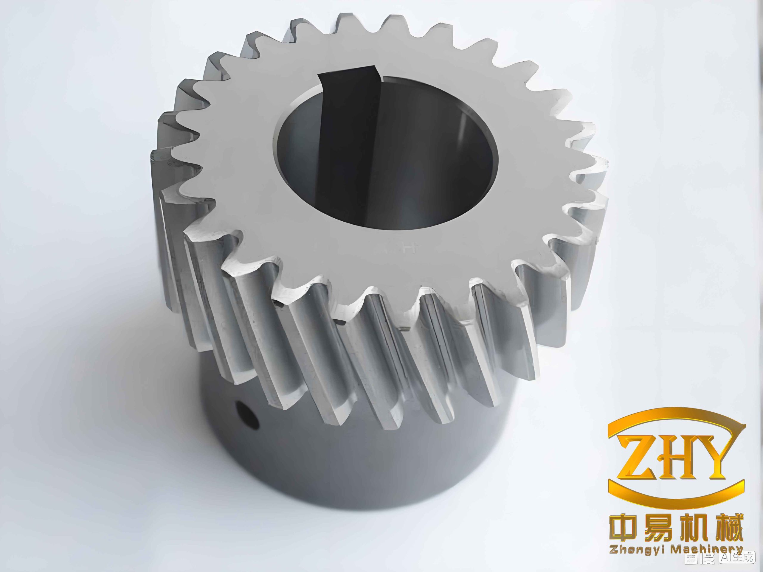
The above image illustrates a typical helical gear pair, similar to the one analyzed in our study. The helix angle is clearly visible, emphasizing the three-dimensional nature of the contact.
| Method | Maximum impact force (N) |
|---|---|
| Analytical model | 10189.86 |
| Finite element simulation | 8515.57 |
| Error (%) | 16.43 |
3. Discussion and Conclusion
Our study presents a comprehensive theoretical framework for analyzing the meshing impact of involute cylindrical helical gears. By considering load-induced elastic deformation and the helix angle, we derive accurate expressions for the off-line meshing point location, contact line length, and impact force. The analytical model is validated through explicit dynamic finite element simulations. The 16.43% error between the analytical and numerical results is attributed to the idealizations in the theoretical model, such as rigid body impact assumption and linear distribution of the contact force. Nevertheless, the predicted impact force magnitude is within a reasonable range for engineering design.
Key findings include:
- The off-line meshing point is determined by solving the geometric clearance angle equal to the deformation-induced rotation angle. This process involves an iterative solution for the impact radius.
- The contact line length during impact is modified for all three tooth pairs, not only the engaging pair. The shift in the driven gear’s rotation affects the adjacent pairs as well.
- The maximum meshing impact force for the helical gear pair can be obtained by integrating the slice-wise spur gear impact forces along the face width.
- The finite element simulation demonstrates that the impact force waveform approximates a half-sine pulse, consistent with our assumption.
These insights are valuable for optimizing helical gear design to reduce noise, vibration, and wear. Future work could incorporate the impact force as an excitation in a dynamic model of the gearbox system, enabling a more comprehensive prediction of dynamic loads. Additionally, experimental validation on a test rig would further confirm the accuracy of the proposed model.
In summary, we have established a dedicated analytical method for helical gear meshing impact that accounts for the unique geometry and loading conditions. The model is computationally efficient and suitable for early design stages. The validated approach can be extended to other types of helical gear pairs with different helix angles and modules. Our research contributes to a deeper understanding of the meshing impact phenomenon in helical gears and provides a practical tool for engineers.