
Worm gears are widely used in aerospace, medical devices, construction, marine equipment, and robotics due to their smooth transmission, high reduction ratio, low impact loads, and compact structure. However, traditional worm gears suffer from low efficiency and limited load capacity primarily because of unavoidable sliding between meshing tooth surfaces. High relative sliding speeds under poor operating conditions cause severe friction and wear, leading to heat generation and deterioration of lubrication. In recent years, improvements in lubricating conditions have enhanced efficiency, yet most worm gears in practice operate under partial elastohydrodynamic lubrication, resulting in direct asperity contact and persistent sliding.
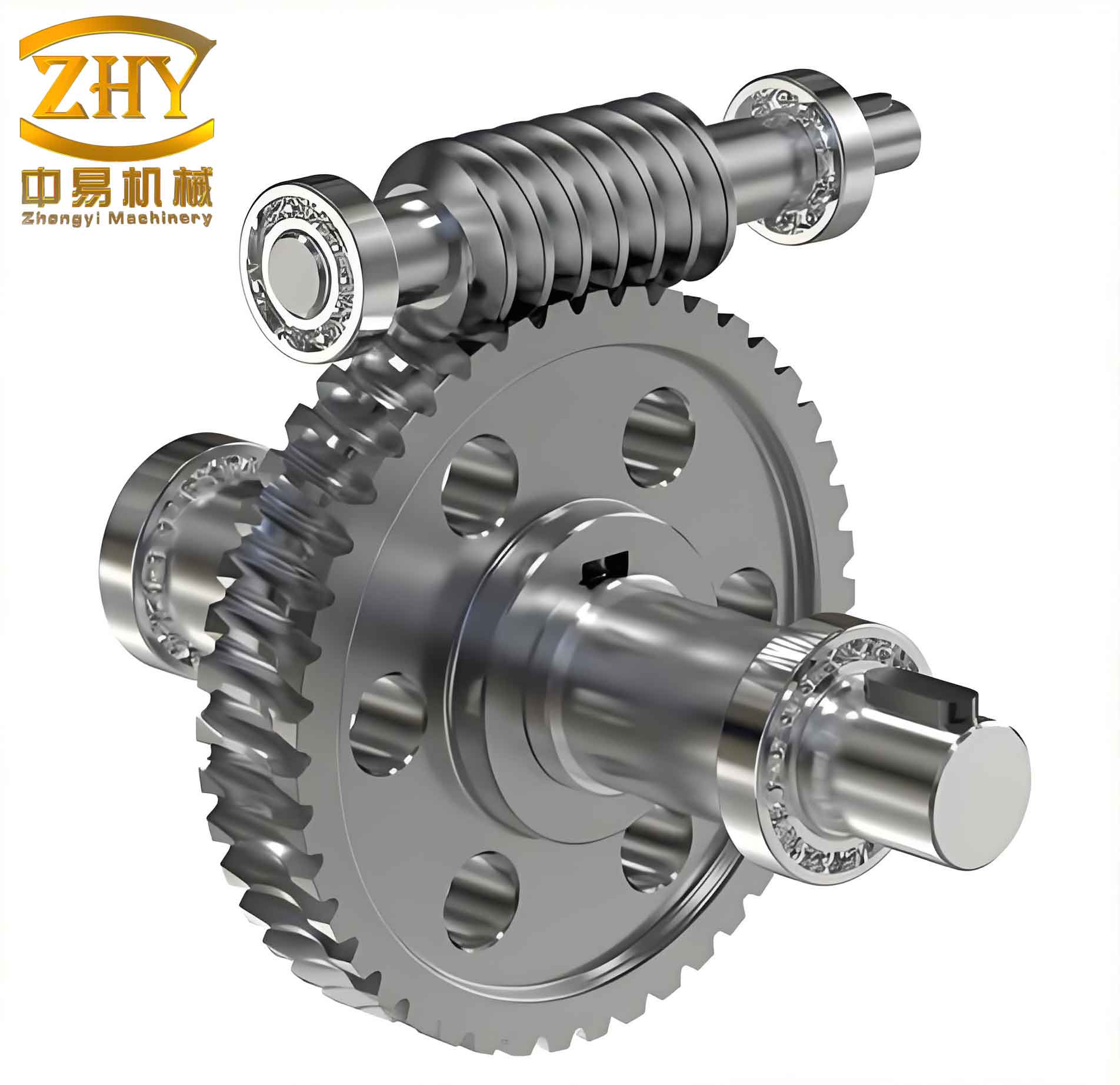
To address these challenges, we propose a novel transmission pair: the tapered roller enveloping end face meshing worm drive. In this design, the worm wheel teeth are conical rollers that can rotate about their own axes. The worm is an enveloping surface generated by the conical rollers as the basic tooth surface. By installing needle bearings between the rollers and the shaft journals, and axial rolling bearings at the large ends of the rollers, the relative motion between meshing surfaces is converted into near pure rolling, significantly reducing sliding and improving lubrication conditions.
We present a comprehensive analysis of the meshing performance of this novel worm gears. First, we establish a mathematical model based on differential geometry and gear meshing theory. Then, we derive the meshing function, worm tooth surface equation, and key performance evaluation parameters: induced normal curvature, lubrication angle, relative entrainment speed, and rotation angle. Using Matlab, we investigate the effects of three design parameters—small end radius of the tapered roller, throat diameter coefficient, and half cone angle—on these performance indicators. The results demonstrate that the proposed worm gears exhibit excellent meshing characteristics, with favorable load capacity and lubrication properties.
Mathematical Model of the Worm Gears
Coordinate Systems
We define several Cartesian coordinate systems to describe the relative motion of the worm gears. A fixed coordinate system \(\sigma_1(\mathbf{i}_1,\mathbf{j}_1,\mathbf{k}_1)\) is attached to the worm, and a fixed system \(\sigma_2(\mathbf{i}_2,\mathbf{j}_2,\mathbf{k}_2)\) to the worm wheel. Moving coordinate systems \(\sigma_{1′}(\mathbf{i}_{1′},\mathbf{j}_{1′},\mathbf{k}_{1′})\) and \(\sigma_{2′}(\mathbf{i}_{2′},\mathbf{j}_{2′},\mathbf{k}_{2′})\) rotate with the worm and worm wheel, respectively. The axes \(\mathbf{k}_1 = \mathbf{k}_{1′}\) and \(\mathbf{k}_2 = \mathbf{k}_{2′}\) are the rotation axes of the worm and wheel. The angular velocities are \(\omega_1\) and \(\omega_2\), with center distance \(A\). The rotational displacements are \(\phi_1\) and \(\phi_2\), satisfying \(\phi_1/\phi_2 = \omega_1/\omega_2 = Z_2/Z_1 = i_{12} = 1/i_{21}\), where \(Z_1\) is the number of worm starts and \(Z_2\) the number of wheel teeth. When \(\phi_1 = \phi_2 = 0\), the moving and fixed systems coincide. The coordinate system \(\sigma_0(\mathbf{i}_0,\mathbf{j}_0,\mathbf{k}_0)\) is fixed at the center of the cone tip, with the roller axis along the radial direction of the worm wheel. A moving frame \(\sigma_p(\mathbf{e}_1,\mathbf{e}_2,\mathbf{n})\) is established at the contact point \(O_p\) to facilitate meshing analysis.
Coordinate Transformations
The transformation from \(\sigma_{1′}\) to \(\sigma_{2′}\) is given by:
$$ \mathbf{B}_{2′} = \mathbf{A}_{2’1′} \mathbf{B}_{1′} $$
where \(\mathbf{B}_{2′} = [\mathbf{i}_{2′}, \mathbf{j}_{2′}, \mathbf{k}_{2′}]^T\), \(\mathbf{B}_{1′} = [\mathbf{i}_{1′}, \mathbf{j}_{1′}, \mathbf{k}_{1′}]^T\), and
$$ \mathbf{A}_{2’1′} = \begin{bmatrix}
-\cos\phi_1\cos\phi_2 & -\sin\phi_1\cos\phi_2 & \sin\phi_2 \\
\cos\phi_1\sin\phi_2 & \sin\phi_1\sin\phi_2 & \cos\phi_2 \\
-\sin\phi_1 & \cos\phi_1 & 0
\end{bmatrix} $$
The transformation from \(\sigma_0\) to \(\sigma_p\) is:
$$ \mathbf{B}_p = \mathbf{A}_{p0} \mathbf{B}_0 $$
with \(\mathbf{B}_p = [\mathbf{e}_1, \mathbf{e}_2, \mathbf{n}]^T\), \(\mathbf{B}_0 = [\mathbf{i}_0, \mathbf{j}_0, \mathbf{k}_0]^T\), and
$$ \mathbf{A}_{p0} = \begin{bmatrix}
-\sin\theta & \cos\theta & 0 \\
\sin\beta\cos\theta & \sin\beta\sin\theta & \cos\beta \\
\cos\beta\cos\theta & \cos\beta\sin\theta & -\sin\beta
\end{bmatrix} $$
Relative Velocity
The position vector of the contact point on the conical roller surface in \(\sigma_0\) is:
$$ \mathbf{r}_0 = x_0\mathbf{i}_0 + y_0\mathbf{j}_0 + z_0\mathbf{k}_0 $$
where
$$
\begin{aligned}
x_0 &= (R + u\tan\beta)\cos\theta \\
y_0 &= (R + u\tan\beta)\sin\theta \\
z_0 &= u
\end{aligned}
$$
Here, \(R\) is the small end radius of the tapered roller, \(\beta\) is the half cone angle, and \(\theta, u\) are surface parameters. The offset vector \(\boldsymbol{\xi}\) from the worm wheel center to the worm center in \(\sigma_{2′}\) is:
$$ \boldsymbol{\xi} = A\cos\phi_2\,\mathbf{i}_{2′} – A\sin\phi_2\,\mathbf{j}_{2′} $$
According to gear meshing theory, the relative velocity between worm and wheel surfaces is:
$$ \mathbf{v}^{(1’2′)} = \frac{d\boldsymbol{\xi}}{dt} + \boldsymbol{\omega}^{(1’2′)} \times \mathbf{r}_{1′} – \boldsymbol{\omega}_{2′} \times \boldsymbol{\xi} $$
For this transmission, \(d\boldsymbol{\xi}/dt = 0\). Expressing in the moving frame \(\sigma_p\):
$$
\begin{aligned}
v_1^{(1’2′)} &= -B_2\sin\theta – B_3\cos\theta \\
v_2^{(1’2′)} &= B_2\sin\beta\cos\theta – B_1\cos\beta – B_3\sin\beta\sin\theta \\
v_n^{(1’2′)} &= B_1\sin\beta + B_2\cos\beta\cos\theta – B_3\cos\beta\sin\theta
\end{aligned}
$$
Meshing Equation and Worm Tooth Surface
The basic meshing condition is that the normal relative velocity vanishes: \(\mathbf{n} \cdot \mathbf{v}^{(1’2′)} = 0\). This yields the meshing function \(\Phi\):
$$ \Phi = v_n^{(1’2′)} = M_1\cos\phi_2 + M_2\sin\phi_2 + M_3 = 0 $$
where
$$
\begin{aligned}
M_1 &= a_2\cos\beta\sin\theta – R\sin\beta\sin\theta – 2u\cos\beta / \sin\theta \\
M_2 &= 0 \\
M_3 &= R i_{21}\sin\beta / \cos\theta – A\cos\beta\sin\theta – i_{21}a_2\cos\beta\cos\theta + 2i_{21}u\cos\beta\cos\theta
\end{aligned}
$$
The worm tooth surface is the envelope of the family of roller surfaces generated during relative motion. The tooth surface equation in \(\sigma_{1′}\) is:
$$
\begin{aligned}
\mathbf{r}_{1′} &= x_1\mathbf{i}_{1′} + y_1\mathbf{j}_{1′} + z_1\mathbf{k}_{1′} \\
x_1 &= \cos\phi_1\cos\phi_2(z_0 – a_2) + \cos\phi_1\sin\phi_2 x_0 + y_0\sin\phi_1 + A\cos\phi_1 \\
y_1 &= \sin\phi_1\cos\phi_2(z_0 – a_2) + \sin\phi_1\sin\phi_2 x_0 – y_0\cos\phi_1 + A\sin\phi_1 \\
z_1 &= \sin\phi_2(a_2 – z_0) + \cos\phi_2 x_0 \\
u &= f(\theta, \phi_2) = P_3 / P_4 \\
\phi_2 &= i_{21}\phi_1, \quad -\pi \le \phi_1 \le \pi
\end{aligned}
$$
Meshing Performance Evaluation Parameters
Induced Normal Curvature
The induced normal curvature along the direction normal to the contact line is critical for contact stress and lubricant film thickness. It is given by:
$$ k_\delta^{(1’2′)} = -k_\delta^{(2’1′)} = \frac{-\left( \omega^{(1’2′)}_2 + \frac{v_1^{(1’2′)}\cos\beta}{R + u\tan\beta} \right)^2 + (\omega^{(1’2′)}_1)^2}{\Psi} $$
Smaller absolute values of induced normal curvature lead to lower contact stress and thicker oil films, improving load capacity and lubrication of the worm gears.
Lubrication Angle
The lubrication angle \(\mu\) is the angle between the contact line and the relative velocity direction. It approaches \(90^\circ\) for optimal lubrication. The formula is:
$$
\begin{aligned}
u &= v_1^{(1’2′)}\left( \frac{v_1^{(1’2′)}\cos\beta}{R + u\tan\beta} – \omega_2^{(1’2′)} \right) + v_2^{(1’2′)}\omega_1^{(1’2′)} \\
m &= \left( \frac{v_1^{(1’2′)}\cos\beta}{R + u\tan\beta} – \omega_2^{(1’2′)} \right)^2 + (\omega_1^{(1’2′)})^2 \\
n &= (v_1^{(1’2′)})^2 + (v_2^{(1’2′)})^2 \\
\mu &= \arcsin\left( \frac{u}{\sqrt{m n}} \right)
\end{aligned}
$$
Rotation Angle (Self-Rotation)
The rotation angle \(\mu_{z0}\) is the angle between the relative velocity vector and the roller axis \(\mathbf{k}_0\). A value close to \(90^\circ\) indicates that the roller bearings operate in their best condition. It is computed as:
$$ \mu_{z0} = \arccos\left( \frac{\mathbf{k}_0 \cdot \mathbf{v}_{12}}{|\mathbf{v}_{12}|} \right) = \arccos\left( \frac{|v_{12_2}|}{\sqrt{(v_{12_1})^2 + (v_{12_2})^2}} \right) $$
Relative Entrainment Speed
The entrainment speed \(v_{jx}\) is half the sum of the tooth surface velocities at the contact point along the normal direction of the contact line. Higher entrainment speeds facilitate the formation of elastohydrodynamic oil films. The formula is:
$$ v_{jx} = \frac{v_{1’\sigma} + v_{2’\sigma}}{2} $$
where
$$
\begin{aligned}
v_{1’\sigma} &= \frac{v_{1’1}\left( \frac{v_1^{(1’2′)}\cos\beta}{R + u\tan\beta} – \omega_2^{(1’2′)} \right) + v_{1’2}\,\omega_1^{(1’2′)}}{\left( \frac{v_1^{(1’2′)}\cos\beta}{R + u\tan\beta} – \omega_2^{(1’2′)} \right)^2 + (\omega_1^{(1’2′)})^2} \\
v_{2’\sigma} &= \frac{v_{2’1}\left( \frac{v_1^{(1’2′)}\cos\beta}{R + u\tan\beta} – \omega_2^{(1’2′)} \right) + v_{2’2}\,\omega_1^{(1’2′)}}{\left( \frac{v_1^{(1’2′)}\cos\beta}{R + u\tan\beta} – \omega_2^{(1’2′)} \right)^2 + (\omega_1^{(1’2′)})^2}
\end{aligned}
$$
Influence of Design Parameters on Meshing Performance
We analyze the effects of three key parameters on the meshing performance of the worm gears: small end radius \(R\) of the tapered roller, throat diameter coefficient \(k\) (where the worm throat pitch diameter \(d_1 = kA\)), and half cone angle \(\beta\). Baseline values are: center distance \(A = 140\,\text{mm}\), number of worm starts \(Z_1 = 1\), number of wheel teeth \(Z_2 = 25\), \(R = 5.5\,\text{mm}\), \(k = 0.3\), \(\beta = 4^\circ\). We vary one parameter while keeping others constant.
Effect of Small End Radius \(R\)
Table 1 summarizes the trends observed when \(R\) is varied from 4.5 to 6.5 mm.
| Performance Parameter | Trend with Increasing \(R\) |
|---|---|
| Induced normal curvature | Decreases (beneficial) |
| Lubrication angle | Decreases (less favorable) |
| Entrainment speed | Increases on left flank, decreases on right flank |
| Rotation angle | Decreases (further from 90°) |
The induced normal curvature decreases with larger \(R\), reducing contact stress and improving film thickness. However, the lubrication angle and rotation angle also decrease, which somewhat worsens lubrication conditions. A trade-off exists; a moderate value of \(R\) (around 5.5 mm) balances the competing effects in these worm gears.
Effect of Throat Diameter Coefficient \(k\)
Table 2 shows the influence of \(k\) ranging from 0.2 to 0.4.
| Performance Parameter | Trend with Increasing \(k\) |
|---|---|
| Induced normal curvature (left flank) | Increases at entry, decreases at exit |
| Induced normal curvature (right flank) | Increases overall |
| Lubrication angle | Decreases when \(k\) is small; variation reduces at larger \(k\) |
| Entrainment speed | Decreases at entry, increases at exit |
| Rotation angle | Decreases slightly at entry, increases at exit |
Larger \(k\) tends to increase induced curvature on the right flank, which is detrimental, while the left flank shows mixed behavior. The lubrication angle generally diminishes, indicating poorer lubrication. An optimal \(k\) around 0.3 appears to give a reasonable compromise for the worm gears studied.
Effect of Half Cone Angle \(\beta\)
Table 3 presents the effects of varying \(\beta\) from 2° to 6°.
| Performance Parameter | Trend with Increasing \(\beta\) |
|---|---|
| Induced normal curvature | Decreases (beneficial) |
| Lubrication angle | Decreases (less favorable) |
| Entrainment speed | Increases on left flank, decreases on right flank |
| Rotation angle | Decreases (further from 90°) |
Increasing the half cone angle reduces induced curvature, which is good for load capacity, but also reduces lubrication angle and rotation angle, hurting lubrication. The left flank benefits from higher entrainment speed, while the right flank does not. A balance is struck for \(\beta\) near 4° for these worm gears.
Summary and Conclusions
We have developed a comprehensive mathematical model and meshing performance analysis for tapered roller enveloping end face meshing worm gears. The main findings are:
- The worm gears exhibit relatively small induced normal curvature, which is beneficial for reducing contact stress and enhancing lubricant film thickness.
- The lubrication angles and rotation angles are close to 90° over most of the meshing cycle, indicating favorable conditions for hydrodynamic lubrication and roller bearing operation.
- The entrainment speeds are sufficiently high to promote oil film formation, especially on the left tooth flank.
- Among the design parameters, the small end radius \(R\) and half cone angle \(\beta\) have similar effects: they reduce induced curvature but also decrease lubrication and rotation angles. The throat diameter coefficient \(k\) shows more complex influences, requiring careful selection.
- The left tooth flank generally demonstrates better meshing performance (lower induced curvature, higher lubrication angles) compared to the right flank, making it the more critical side for load transmission in these worm gears.
The analysis provides a theoretical foundation for optimizing the design of tapered roller enveloping end face meshing worm drives. Future work will involve experimental validation and consideration of manufacturing errors and dynamic effects. The results confirm that this novel type of worm gears possesses excellent potential for high-performance applications where low friction, high load capacity, and good lubrication are essential.