1. Introduction
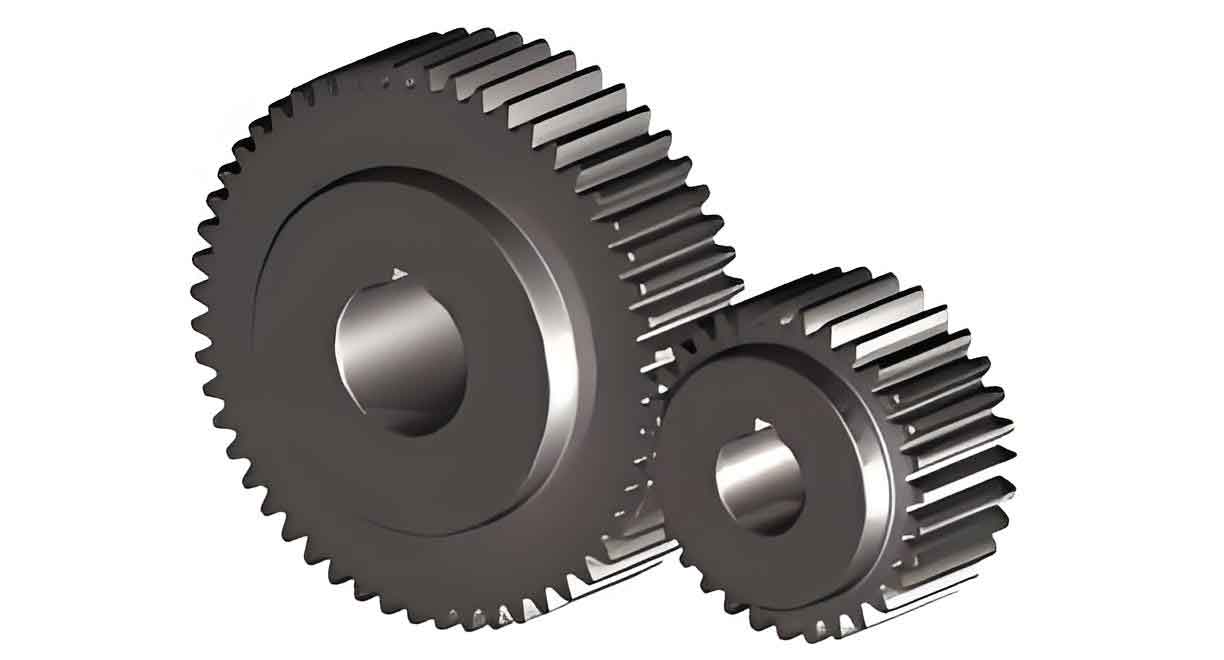
Spur gear is fundamental components in mechanical transmission systems due to their compact structure, high efficiency, and reliability. However, wear during meshing operations remains a critical challenge, often leading to gear failure and costly downtime. Traditional wear detection methods, such as coordinate measuring machines (CMMs) or wavelet thresholding combined with genetic algorithms, face limitations in accuracy, computational efficiency, and adaptability to dynamic conditions. To address these issues, this study proposes a novel method for detecting the meshing wear state of spur gear using improved spectral residuals. This approach integrates dynamic modeling, image processing, and machine learning to enhance detection accuracy and reduce processing time.

2. Dynamic Modeling of Spur Gear Meshing System
2.1 Dynamic Equations
The dynamic behavior of spur gear is modeled by considering friction torque, stiffness, and damping coefficients. The governing equations for the active and driven gears are derived as follows:
For the active gear:Ipθ¨p=Tp−Rp∑i=1nzFi−∑i=1nzΛiρpiμiFiIpθ¨p=Tp−Rpi=1∑nzFi−i=1∑nzΛiρpiμiFi
For the driven gear:Igθ¨g=Rg∑i=1nzFi+∑i=1nzΛiρgiμiFi−TgIgθ¨g=Rgi=1∑nzFi+i=1∑nzΛiρgiμiFi−Tg
Key Parameters:
| Symbol | Description |
|---|---|
| Ip,IgIp,Ig | Moment of inertia (active/driven gear) |
| Tp,TgTp,Tg | Input/output torque |
| Rp,RgRp,Rg | Base circle radii |
| ΛiΛi | Direction function |
| ρpi,ρgiρpi,ρgi | Friction arms |
| μiμi | Friction coefficient |
The meshing force FiFi is defined as:Fi=ki(t)⋅f(δ)+ci(t)⋅f(δ˙)Fi=ki(t)⋅f(δ)+ci(t)⋅f(δ˙)
where ki(t)ki(t) and ci(t)ci(t) represent time-varying stiffness and damping.
2.2 Direction Function and Friction Analysis
The direction function ΛiΛi determines the relative motion between gear pairs:Λi=sign(v1−v2)={1v1>v20v1=v2−1v1<v2Λi=sign(v1−v2)=⎩⎨⎧10−1v1>v2v1=v2v1<v2
Here, v1v1 and v2v2 are tangential velocities at meshing points.
3. Image Processing for Spur Gear Wear Detection
3.1 Preprocessing: Noise Reduction and Binarization
Raw images of spur gear meshing surfaces are prone to noise. Adaptive binarization is applied to separate wear regions from the background. A Gaussian filter smooths the image:G(x,y)=12πδ2exp(−x2+y22δ2)G(x,y)=2πδ21exp(−2δ2x2+y2)
where δδ controls the smoothing intensity.
3.2 Improved Spectral Residual Edge Detection
The spectral residual method is enhanced to identify wear edges by maximizing gradient magnitudes. Key steps include:
- Gradient Calculation:M(i,j)=Px(i,j)2+Py(i,j)2,θ(i,j)=arctan(Py(i,j)Px(i,j))M(i,j)=Px(i,j)2+Py(i,j)2,θ(i,j)=arctan(Px(i,j)Py(i,j))
- Non-Maximum Suppression (NMS):N(i,j)=NMS[M(i,j),θ(i,j)]N(i,j)=NMS[M(i,j),θ(i,j)]
- Edge Linking: Dual thresholds (ThTh and Tl=0.4ThTl=0.4Th) classify edge pixels.
4. Workflow for Spur Gear Wear State Detection
4.1 Feature Extraction and Neural Network Training
Wear features (e.g., flank wear, surface roughness, gear spacing) are extracted from images under varying operating conditions. A neural network is trained to map these features to wear severity levels.
| Feature | Description |
|---|---|
| Flank wear | Micron-level deviations on tooth surfaces |
| Surface roughness | RaRa values from profilometry |
| Gear spacing | Changes in center distance due to wear |
4.2 Detection Algorithm
The workflow integrates dynamic modeling and image processing:
- Acquire spur gear images before and after wear.
- Preprocess images using Gaussian filtering and binarization.
- Detect edges via improved spectral residuals.
- Extract wear features and input them into the neural network.
- Predict wear state and remaining service life.
5. Experimental Validation
5.1 Comparative Analysis of Detection Accuracy
Three methods were tested:
- CMM-based method [4]
- Wavelet-GA-SVM method [5]
- Proposed improved spectral residual method
| Method | Average Accuracy (%) |
|---|---|
| CMM [4] | 71 |
| Wavelet-GA-SVM [5] | 77 |
| Proposed | 91 |
The proposed method outperforms others due to its integration of dynamic modeling and advanced edge detection.
5.2 Computational Efficiency
Processing time was measured across 500 iterations:
| Method | Detection Time (s) |
|---|---|
| CMM [4] | 32 |
| Wavelet-GA-SVM [5] | 42 |
| Proposed | 20 |
The improved spectral residual method reduces time by 37.5–52.4% compared to traditional approaches.
6. Discussion
6.1 Advantages of the Proposed Method
- High Accuracy: Dynamic modeling captures real-time wear mechanisms.
- Speed: Spectral residuals enable rapid edge detection.
- Adaptability: Neural networks generalize across diverse spur gear configurations.
6.2 Limitations and Future Work
- Requires high-resolution images for precise edge detection.
- Future studies could incorporate real-time oil debris monitoring for holistic wear analysis.
7. Conclusion
This study presents a robust method for detecting the meshing wear state of spur gear using improved spectral residuals. By combining dynamic modeling, image processing, and machine learning, the method achieves 91% accuracy with a 20-second processing time, outperforming existing techniques. This advancement holds significant potential for predictive maintenance in industries reliant on spur gear systems.
Appendix: Key Formulas Summary
| Formula | Description |
|---|---|
| Ipθ¨p=Tp−Rp∑Fi−∑ΛiρpiμiFiIpθ¨p=Tp−Rp∑Fi−∑ΛiρpiμiFi | Active gear dynamics |
| M(i,j)=Px2+Py2M(i,j)=Px2+Py2 | Gradient magnitude |
| N(i,j)=NMS[M(i,j),θ(i,j)]N(i,j)=NMS[M(i,j),θ(i,j)] | Non-maximum suppression |
| G(x,y)=12πδ2exp(−x2+y22δ2)G(x,y)=2πδ21exp(−2δ2x2+y2) | Gaussian smoothing |
