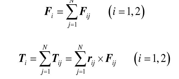
Taking any slice gear pair in Fig. 1 as an example, the calculation method of micro element meshing force FIJ is described in detail. The load-bearing deformation of gears makes a pair of teeth enter and exit meshing ahead of time, and the actual meshing interval is longer than the theoretical meshing interval, so it is called extended meshing or out of line meshing. As shown in Fig. 2, due to the elastic deformation of tooth pair 2, tooth pair 1 enters meshing before the theoretical meshing point (point B), and tooth pair 3 exits meshing after the theoretical meshing point (point E). In addition, with the increase of transmission load, the increase of coincidence degree is greater. The gear tooth separation distance (gtsd) is defined as the distance between a pair of teeth that are about to enter or just exit meshing when there is no elastic deformation. The meshing spacing is measured along the meshing line, as shown in Figure 2 for SA and Sr.
In order to calculate the elastic deformation of the teeth of the thin-walled gear pair, two coordinate systems need to be established, the fixed coordinate system oxy, the follow-up coordinate system o1jxy, and the rotation angle from ray ox to ray o1jx is γ (counterclockwise is positive), as shown in Figure 3. The actual meshing state of a pair of thin-walled gear pairs is shown by the solid line in the figure. If the gear O2J is fixed and the tooth has no elastic deformation, the theoretical position of gear o1j is shown by the dotted line in the figure, and the length of line CD represents the transfer error. Because the transmission error of different tooth pairs of the same gear pair on the meshing line is the same, so | GH | = | CD | = te. Because the tooth pair 1 is outside the theoretical meshing range be, the meshing distance of tooth pair 1 is as when there is no elastic deformation, so the elastic deformation of tooth pair 1 on the meshing line is δ 1 ˆ = te SA. Since the tooth surface error and the influence of tooth shedding during gear operation have not been included in the formula, the “^” symbol is used to distinguish it from the formula.
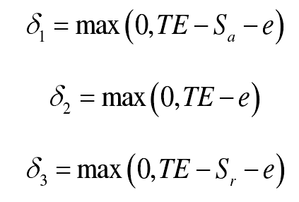
Out of line meshing only changes the end point and start point of the single tooth meshing zone, but does not affect the original double tooth meshing zone. Therefore, according to the position of the tooth on the meshing line, the elastic deformation is calculated in three situations: 1) before entering the theoretical meshing zone (before point B); 2) between the theoretical meshing zone (between point B and point E); 3) after exiting the theoretical meshing zone (after point E).

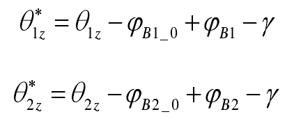
Where, δ I (I = 1,2,3) is the elastic deformation of the above three kinds of teeth, δ I ≥ 0 is the contact of tooth surface, and δ I < 0 is the separation of tooth surface; te is the transfer error, which is calculated with [x1y1 θ 1zx2y2 θ 2Z] t as the independent variable in the fixed coordinate system, and the specific formula is longer; SA and SR are the meshing distance, which is calculated with [a θ 1z θ 2Z] as the independent variable in the follow-up coordinate system (a θ 1z θ 2Z)) E is the tooth surface deviation, which comes from the gear machining error or tooth surface modification. The transformation formula of angular displacement in fixed coordinate system and follow-up coordinate system is as follows:

Where, ψ B1, ψ B2 and γ are shown in Fig. 3_ 0 is the value of ψ B1 and ψ B2 at standard center distance_ 0 is the same.

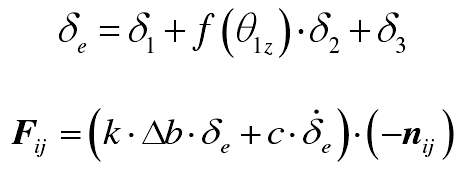
In conclusion, the micro meshing force of sheet gear pair is

In the formula, f () = 2 in double tooth meshing and f () = 1 in single tooth meshing; K is the meshing stiffness of unit tooth width line, which is calculated according to the formula on page 72 of ISO 6336-1-2006; Δ B is the tooth width of sheet gear pair; C is the meshing damping coefficient, which is calculated according to the formula; NIJ is the unit vector of external normal of sheet gear Oij.


