
Face gears represent a class of transmission elements that have gradually attracted significant attention in recent decades because of their unique geometric configuration and outstanding load-sharing capability. Unlike conventional involute cylindrical gears, face gears are generated by a shaper cutter and mate with a spur involute pinion under point contact conditions. This distinctive meshing behavior provides face gears with remarkable advantages in split-torque transmission systems, particularly in rotorcraft main reducers, where compactness, low weight, and high reliability are simultaneously required. In my research, I focus on the influence of tooth surface micro-textures on the dynamic performance of face gear transmissions, with the aim of establishing a systematic understanding that links micro-texture geometry to internal excitations and, ultimately, to the nonlinear dynamic response of the whole system.
Reducing friction and improving reliability under high-load and high-speed conditions remain central challenges for face gears used in extreme service environments. Micro-texturing technology has already demonstrated considerable potential in tribological applications by generating hydrodynamic pressure, storing lubricant, capturing wear debris, and promoting secondary lubrication. However, most existing studies concentrate on the friction-reduction effect of micro-textures and neglect the coupling between micro-texture geometry and the dynamic contact characteristics of face gears. This gap motivates my investigation, in which I treat the time-varying meshing stiffness and the transmission error as the two principal internal excitations that govern the dynamic behavior of micro-textured face gears.
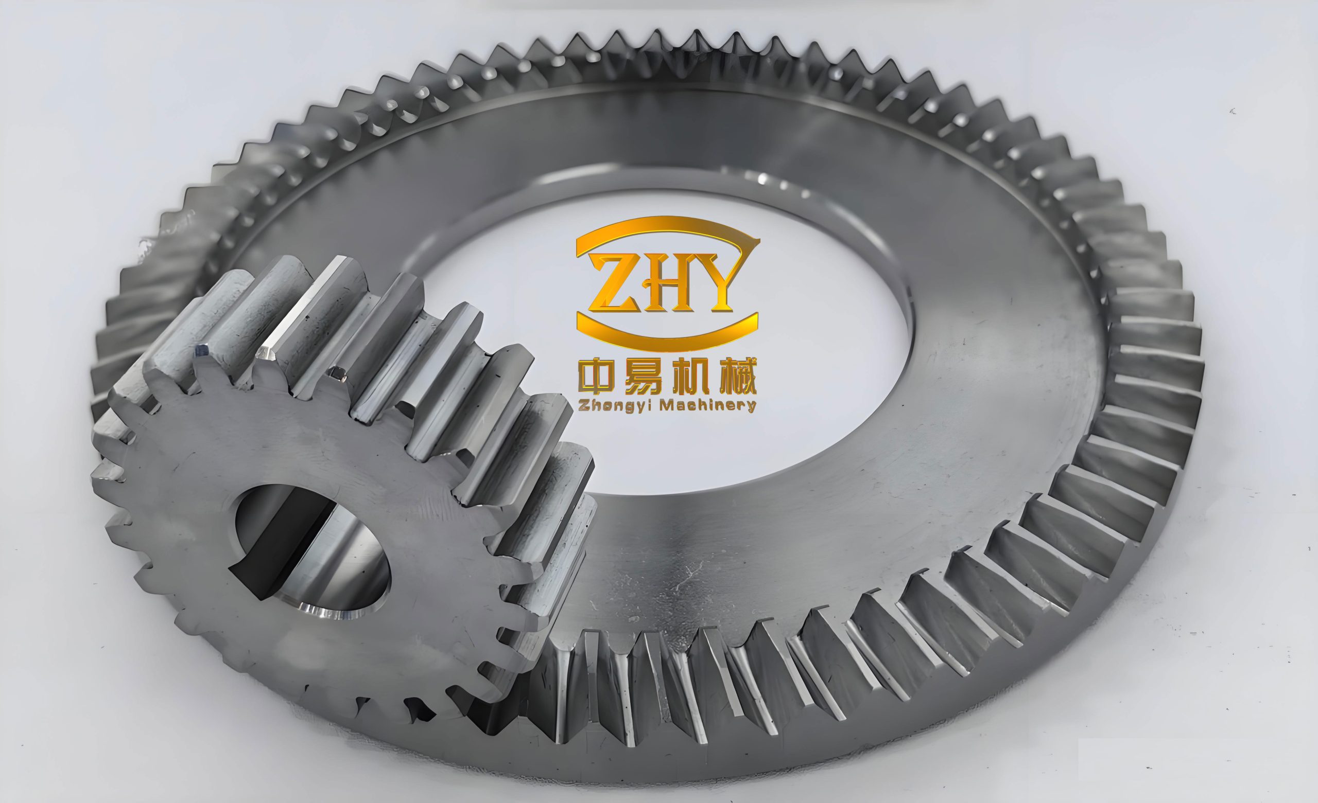
Generation of the Face Gear Tooth Surface and Meshing Trajectory
Because the tooth surface of a face gear is a complex curved surface with variable curvature, no direct modeling method can be applied without first deriving the theoretical tooth surface. I therefore begin from the shaper cutter generation principle. During the generation process, the shaper cutter rotates about its own axis while reciprocating along the axis of the mating pinion, and the face gear rotates simultaneously about its axis. The relationship between the rotation angle of the shaper cutter and that of the face gear is expressed as
$$\phi_2 = \frac{N_S}{N_2}\,\phi_S$$
where \(N_S\) and \(N_2\) denote the tooth numbers of the shaper cutter and the face gear, respectively. The tooth surface of the shaper cutter is an involute helicoid, and its position vector can be written in the cutter coordinate system as
$$\mathbf{r}_S(u_S,l_S)=\begin{bmatrix} r_{bS}[\sin(u_0+u_S)-u_S\cos(u_0+u_S)] \\ -r_{bS}[\cos(u_0+u_S)+u_S\sin(u_0+u_S)] \\ u_S l_S \\ 1 \end{bmatrix}$$
where \(r_{bS}\) is the base radius of the shaper cutter, \(u_S\) is the involute roll parameter, \(l_S\) is the axial parameter, and \(u_0\) is the angular offset defined by
$$u_0 = \frac{\pi}{2N_S} – \mathrm{inv}\,\alpha_S$$
with \(\alpha_S\) denoting the pressure angle and \(\mathrm{inv}\,\alpha_S = \tan\alpha_S – \alpha_S\). The unit normal vector of the shaper cutter tooth surface is obtained from the partial derivatives of the position vector as
$$\mathbf{n}_S=\frac{\partial \mathbf{r}_S}{\partial u_S}\times\frac{\partial \mathbf{r}_S}{\partial l_S}\Big/\left\|\frac{\partial \mathbf{r}_S}{\partial u_S}\times\frac{\partial \mathbf{r}_S}{\partial l_S}\right\|$$
By applying the homogeneous coordinate transformation matrix \(M_{2S}\), the shaper cutter tooth surface is mapped into the face gear coordinate system:
$$\mathbf{r}_2(u_S,l_S,\phi_S)=M_{2S}\,\mathbf{r}_S(u_S,l_S)$$
The transformation matrix \(M_{2S}\) is the product of three elementary matrices:
$$M_{2S}=M_{2p}M_{pm}M_{mS}$$
with
$$M_{2p}=\begin{bmatrix} \cos\phi_2 & \sin\phi_2 & 0 & 0 \\ -\sin\phi_2 & \cos\phi_2 & 0 & 0 \\ 0 & 0 & 1 & 0 \\ 0 & 0 & 0 & 1 \end{bmatrix},\quad M_{pm}=\begin{bmatrix} 1 & 0 & 0 & 0 \\ 0 & \cos\gamma_m & -\sin\gamma_m & 0 \\ 0 & \sin\gamma_m & \cos\gamma_m & 0 \\ 0 & 0 & 0 & 1 \end{bmatrix}$$
$$M_{mS}=\begin{bmatrix} \cos\phi_S & -\sin\phi_S & 0 & 0 \\ \sin\phi_S & \cos\phi_S & 0 & 0 \\ 0 & 0 & 1 & 0 \\ 0 & 0 & 0 & 1 \end{bmatrix}$$
According to the theory of gearing, the meshing condition requires that the common normal at the contact point be perpendicular to the relative velocity vector:
$$\mathbf{n}_S\cdot\mathbf{v}_S^{(S2)}=0$$
where the relative velocity is the difference between the velocity of the shaper cutter and that of the face gear expressed in the cutter coordinate system:
$$\mathbf{v}_S^{(S2)}=\mathbf{v}_S^{(S)}-\mathbf{v}_S^{(2)}$$
Combining the meshing equation with the transformed tooth surface yields the meshing equation of the face gear:
$$f(l_S,u_S,\phi_S)=\mathbf{n}_S\cdot\mathbf{v}_S^{(S2)}=0$$
Solving this equation together with the surface representation gives the working tooth surface of the face gear. The meshing trajectory of the face gear pair coincides with the contact path generated by the shaper cutter, since the tooth number of the pinion does not alter the meshing path geometry. For the parameter set used in my study, the meshing trajectory is a smooth curve located approximately at a radius of \(94.5\,\mathrm{mm}\) from the face gear axis.
I selected the basic parameters of the face gear pair as listed in Table 1. The module was fixed at \(3.9\,\mathrm{mm}\) because this is currently the only module for which face gears can be manufactured to grade 5 accuracy, and all subsequent simulations, dynamic solutions, and vibration experiments were therefore conducted on this configuration.
| Parameter | Unit | Value |
|---|---|---|
| Pinion tooth number | – | 21 |
| Face gear tooth number | – | 48 |
| Shaper cutter tooth number | – | 22 |
| Module | mm | 3.9 |
| Pressure angle | deg | 25 |
| Inner radius of face gear | mm | 90 |
| Meshing trajectory radius | mm | 94.5 |
Substituting these parameters into the derived tooth surface equations produces a dense point cloud of the working surface. After importing the point cloud into a solid modeling environment and applying array and filling operations, I obtained the three-dimensional model of the face gear. Because the face gear also exhibits undercutting and tooth tip sharpening, the inner and outer radii must be limited according to the standard tooth width design criteria. The working surface participates in meshing, whereas the transition surface serves to avoid stress concentration at the tooth root.
To validate the theoretical meshing trajectory, I performed a contact simulation under a boundary condition of \(10\,\mathrm{N\cdot m}\) applied to the face gear. The mesh size was set to \(0.8\,\mathrm{mm}\). The simulation showed that the contact stress concentration is located at a radius of approximately \(94\,\mathrm{mm}\), which agrees well with the theoretically predicted meshing trajectory. The contact stress distribution takes the form of an elliptical contact zone centered on the meshing point, which is consistent with Hertzian contact theory. The maximum stress point lies on the theoretical meshing trajectory, which confirms that the micro-textures intended to improve lubrication should be distributed over the entire working tooth surface of the face gear.
Design and Modeling of the Tooth Surface Micro-Texture
The micro-texture patterns most commonly used to enhance hydrodynamic lubrication in gears can be classified into three categories: pits, protrusions, and grooves. Considering the wear resistance and manufacturability requirements of face gears under extreme service conditions, I focused on circular pit-shaped micro-textures. Based on the meshing trajectory obtained above, I designed the texture layout so that the micro-textures are distributed as uniformly as possible along the meshing trajectory. This ensures that the analysis captures the influence of the micro-structure at the location of maximum contact pressure.
Because the tooth surface is a complex curved surface, I projected each texture pattern onto a reference plane and then wrapped it onto the tooth surface. The principal design parameters are the pit diameter \(D\), the pit depth \(H\), the pit spacing \(L\), and the number of pits along the tooth height direction \(N\). The designed micro-textures are nominally circular in the projection plane; after wrapping onto the curved face gear tooth surface, they remain approximately circular.
Under a simulation boundary condition corresponding to a face gear load of \(100\,\mathrm{N\cdot m}\), I observed that the introduction of micro-textures increases the contact stress by approximately \(35\%\), although the overall form of the contact stress distribution does not change significantly. This indicates that micro-textures locally intensify the contact pressure at their edges while preserving the global elliptical contact pattern characteristic of face gears.
Influence of Micro-Texture Parameters on Time-Varying Meshing Stiffness
The time-varying meshing stiffness of face gears cannot be calculated directly from the standard for involute cylindrical gears because the face gear tooth surface is a free-form surface and the contact is a point contact. Among the available approaches, the strain energy method, the transmission error method, and the numerical-analytical method are the most widely used. In my work, I adopted the strain energy method implemented through finite element simulation because it provides a direct relationship between the elastic strain energy stored in the meshing teeth and the equivalent meshing stiffness.
In a static structural analysis, the strain energy is integrated from the deformation of each mesh element in all degrees of freedom. The bending, shear, and axial compression stiffnesses can therefore be expressed as
$$K_b=\frac{F^2}{2U_b},\qquad K_S=\frac{F^2}{2U_S},\qquad K_a=\frac{F^2}{2U_a}$$
Because only the gear teeth are retained in the simulation, the deformation of the gear foundation is neglected, and the Hertzian contact stiffness is also neglected because the contact area of face gears under heavy load is relatively large. The equivalent time-varying meshing stiffness of the face gear pair is then obtained from
$$K=\frac{F^2}{2\left(U_a+U_b+U_S\right)}$$
Using this formulation, I first analyzed the meshing behavior of an untextured face gear. The time-varying meshing stiffness curve is approximately sinusoidal, and the introduction of micro-textures reduces the overall stiffness amplitude by about \(15\%\). The force distribution among the teeth reveals that the face gear pair passes through single-tooth, double-tooth, and even triple-tooth contact zones during one meshing cycle. When the face gear pair is in the triple-tooth contact stage, the time-varying meshing stiffness reaches its minimum value. This multi-tooth contact behavior explains why face gears operate more smoothly and possess higher load-carrying capacity than conventional gears.
I then conducted single-factor experiments to isolate the influence of each micro-texture parameter. The results show that the influence of micro-textures on the time-varying meshing stiffness is concentrated at the peaks and valleys of the stiffness curve, with the valley region being more strongly affected. Comparison with the contact stress distribution indicates that the unmodified face gear develops stress concentration at the tooth tip during meshing, and the micro-textures modify this stress concentration, thereby altering the meshing stiffness. Among the design parameters, the pit diameter \(D\) and the number of pits along the tooth height \(N\) are the two most influential factors, and the stiffness decreases as both \(D\) and \(N\) decrease. The influence of the pit depth \(H\) is less pronounced, with a maximum stiffness observed at \(H=0.3\,\mathrm{mm}\).
| Parameter | Trend with increasing parameter | Relative influence |
|---|---|---|
| Pit diameter \(D\) | Stiffness decreases | Strong |
| Pit depth \(H\) | Maximum near 0.3 mm | Moderate |
| Number along tooth height \(N\) | Stiffness decreases | Strong |
| Pit spacing \(L\) | Optimum near 1.04 mm | Moderate to strong |
Influence of Micro-Texture Parameters on Transmission Error
Transmission error is defined as the difference between the actual rotation angle of the driven gear and its ideal rotation angle. It originates from manufacturing errors, assembly errors, and elastic deformation. For a face gear pair, the transmission error can be expressed in terms of the angular positions of the pinion and the face gear as
$$TE=\theta_g-\frac{z_p}{z_g}\theta_p$$
To express the transmission error along the line of action, the loaded transmission error is written as
$$LTE=\left(\theta_g-\frac{z_p}{z_g}\theta_p\right)R_g$$
Because a face gear has no base circle in the conventional sense, the equivalent radius \(R_g\) is evaluated at the meshing trajectory radius as
$$R_g=R_m\cos\alpha_n$$
where \(R_m\) is the meshing trajectory radius and \(\alpha_n\) is the normal pressure angle. In my simulation, \(R_m\) was taken as \(94.5\,\mathrm{mm}\).
The simulation procedure to obtain the loaded transmission error consists of three steps. First, all degrees of freedom of the face gear are constrained, and a small rotational displacement is applied to the pinion to eliminate the initial gap between the mating teeth. Second, the pinion is fully constrained, the rotational degree of freedom of the face gear is released, and the load torque is gradually increased to the target value. Third, the rotational degree of freedom of the pinion is released while the boundary conditions of the face gear are maintained, and the rotational displacement is applied step by step to compute the angular positions at different meshing positions. This procedure eliminates the backlash caused by mesh discretization and yields the theoretical transmission error of the face gear pair.
The results show that the introduction of micro-textures reduces the loaded transmission error of the face gear pair by approximately \(13.5\%\). This trend is consistent with observations reported for spur gears with bio-inspired micro-textures. However, the variation of the transmission error with the individual texture parameters does not exhibit a clear monotonic trend, and no obvious optimization direction can be identified from the single-factor experiments alone. Notably, the locations at which the micro-textures affect the transmission error coincide with those at which they affect the time-varying meshing stiffness, namely the peaks and valleys of the corresponding curves.
To provide the internal excitations required by the dynamic model, I fitted the time-varying meshing stiffness and the transmission error using Fourier series. The stiffness is represented as
$$k(t)=k_m+\sum_{l=1}^{N_k}A_{kl}\cos\left(l\omega_h t+\Phi_{kl}\right)$$
and the static transmission error is represented as
$$e_n(t)=e_m+\sum_{l=1}^{N_e}A_{el}\cos\left(l\omega_h t+\Phi_{el}\right)$$
where \(k_m\) and \(e_m\) are the mean values, \(A_{kl}\) and \(A_{el}\) are the harmonic amplitudes, \(\omega_h\) is the meshing angular frequency, and \(\Phi_{kl}\) and \(\Phi_{el}\) are the phase angles.
Response Surface Analysis and Sensitivity of Micro-Texture Parameters
Because the micro-texture parameters are strongly coupled, it is difficult to determine whether a change in dynamic performance is caused by a single parameter. I therefore employed response surface methodology to investigate the coupled influence of the design parameters and to identify the optimization direction. The parameter ranges used in the optimization are listed in Table 2.
| Parameter | Unit | Range |
|---|---|---|
| Pit diameter \(D\) | mm | 0.4–0.8 |
| Pit depth \(H\) | mm | 0.1–0.3 |
| Pit spacing \(L\) | mm | 0.8–1.2 |
| Number along tooth height \(N\) | – | 3–8 |
For the diameter–depth–number combination, I used a Box–Behnken sampling scheme, which places sample points at the midpoints of the edges of a cube and thereby avoids the extreme distances that can occur in other designs. The resulting response surfaces show that the trends observed in the single-factor experiments are preserved. The variation of the meshing stiffness with the texture parameters is approximately \(5\%\). The number of textures along the tooth height \(N\) has only a negligible influence on the meshing stiffness, whereas \(D\) and \(H\) exhibit more pronounced effects. The global sensitivity analysis confirms that the influence of \(N\) is almost negligible compared with those of \(D\) and \(H\). This finding provides guidance for the layout design of micro-textures on face gear tooth surfaces: when textures are machined on the tooth surface away from the tooth root, the texture density does not strongly affect the meshing stiffness.
The fitted response surface for the diameter–depth–number combination is given by
$$y = 1432680.81 – 1720720.03\,x_1 – 15652694.67\,x_2 + 3143262.80\,x_3$$
where \(x_1\) represents \(N\), \(x_2\) represents \(D\), and \(x_3\) represents \(H\), and \(y\) is the meshing stiffness. The accuracy of the approximate model is summarized in Table 3.
| Evaluation metric | Value | Acceptance criterion |
|---|---|---|
| \(R^2\) | 0.97918 | > 0.9 |
| RMSE | 0.08984 | < 0.2 |
| MAE | 0.17895 | < 0.3 |
For the diameter–depth–spacing combination, I adopted an optimized Latin hypercube sampling scheme based on the maximin criterion and selected fifty design points. The corresponding response surfaces exhibit multiple optimization directions, and the coupled influence of diameter, depth, and spacing on the meshing stiffness can reach \(102\%\). When the texture spacing is approximately \(1.04\,\mathrm{mm}\), the meshing stiffness attains its maximum value, and elliptical contour lines are clearly visible in the response surface. The sensitivity analysis shows that the meshing stiffness is most sensitive to the texture depth and least sensitive to the texture diameter. When the micro-structure is shallow, the material deformation quickly reaches the bottom of the micro-structure, which reduces the micro-slip along the meshing direction and consequently reduces the transmission error at the macroscopic level.
The fitted third-order polynomial regression model for this combination is
$$y = 2952584994.00 – 109197886.83\,x_1 – 4348880645.41\,x_2 – 1220568737.82\,x_3 + 1903673250.03\,x_1^2 + 4852997342.81\,x_2^2 + 2035239701.98\,x_3^2 – 264165176.92\,x_1x_2 – 205581850.56\,x_1x_3 – 123761576.37\,x_2x_3 – 3328465411.46\,x_1^3 – 17454268.47\,x_2^3 – 1065642612.77\,x_3^3$$
where \(x_1\), \(x_2\), and \(x_3\) denote the depth, spacing, and diameter, respectively, and \(y\) denotes the meshing stiffness. The accuracy metrics are listed in Table 4.
| Evaluation metric | Value | Acceptance criterion |
|---|---|---|
| \(R^2\) | 0.91214 | > 0.9 |
| RMSE | 0.09294 | < 0.2 |
| MAE | 0.21238 | < 0.3 |
Based on the two sets of response surface experiments, I conclude that micro-textures with smaller diameters and shallower depths reduce the weakening effect on the meshing stiffness. There exists an optimal value of the texture spacing, which is approximately \(1.04\,\mathrm{mm}\), whereas the texture density has only a minor influence on the time-varying meshing stiffness and can therefore be used as a key control parameter for improving friction-reduction and lubrication performance. The time-varying meshing stiffness and transmission error obtained in this chapter can be fitted by Fourier series and used as internal excitations in the dynamic model of the face gear transmission system.
Nonlinear Dynamic Modeling of the Face Gear Transmission System
To investigate the influence of tooth surface micro-textures on the dynamic response of face gears, I established a lumped-parameter dynamic model of an orthogonal face gear transmission system. The model consists of six degrees of freedom, namely the translational displacements of the pinion along the \(x\) and \(z\) directions, the translational displacements of the face gear along the same directions, and the rotational displacements of the pinion and the face gear about their respective axes:
$$\mathbf{X}=\begin{bmatrix} X_1 & Z_1 & \theta_{y1} & X_2 & Z_2 & \theta_{z2} \end{bmatrix}^{\mathrm{T}}$$
The pinion and the face gear rotate about the \(y\) and \(z\) axes, respectively. Because the pinion in a face gear pair does not experience axial force and the face gear does not experience radial force, the shafts are supported by bearings that are modeled as springs and dampers. The model incorporates backlash, time-varying meshing stiffness, and static transmission error.
The dynamic load along the line of action is expressed as
$$F_n=\bar{k}(t)\,f(\bar{X}_n)+c_m\dot{\bar{X}}_n$$
and its components along the coordinate axes are
$$F_x=F_n\cos\alpha,\qquad F_z=F_n\sin\alpha$$
The backlash function is piecewise linear and is written as
$$f(\bar{X}_n)=\begin{cases} \bar{X}_n-b_c, & \bar{X}_n>b_c \\ 0, & -b_c\le \bar{X}_n\le b_c \\ \bar{X}_n+b_c, & \bar{X}_n<-b_c \end{cases}$$
The relative displacement along the normal direction is
$$\bar{X}_n=X_1\cos\alpha+Z_1\sin\alpha+r_{b1}\theta_{y1}+X_2\cos\alpha+Z_2\sin\alpha-r_m\theta_{z2}-e_n(t)$$
Applying Newton’s second law to each degree of freedom yields the governing equations of the face gear system:
$$m_1\ddot{X}_1+c_{x1}\dot{X}_1+k_{x1}X_1=F_x$$
$$m_1\ddot{Z}_1+c_{z1}\dot{Z}_1+k_{z1}Z_1=F_z$$
$$I_{1y}\ddot{\theta}_{y1}=T_1+F_n r_{b1}$$
$$m_2\ddot{X}_2+c_{x2}\dot{X}_2+k_{x2}X_2=-F_x$$
$$m_2\ddot{Z}_2+c_{z2}\dot{Z}_2+k_{z2}Z_2=-F_z$$
$$I_{2z}\ddot{\theta}_{z2}=T_2-F_n r_m$$
Combining these equations with the relative displacement expression transforms the torsional displacements into an expression involving the backlash, the time-varying meshing stiffness, and the static transmission error:
$$m_e\ddot{\bar{X}}_n+a_1^2k(t)f(\bar{X}_n)+a_1^2c_m\dot{\bar{X}}_n+a_1F_1(t)+m_e\ddot{e}_n(t)=0$$
where the equivalent mass \(m_e\) is defined as
$$m_e=\frac{1}{\dfrac{1}{m_1}+\dfrac{1}{m_2}+\dfrac{r_{b1}^2}{I_{1y}}+\dfrac{r_m^2}{I_{2z}}}$$
and the total dynamic load is represented by the Fourier series
$$F_1(t)=F_{1m}+F_{1v}=F_{1m}+\sum_{l=1}^{N_F}A_{Fl}\cos\left(l\omega_F t+\Phi_{Fl}\right)$$
Because the physical quantities in the governing equations span several orders of magnitude, I nondimensionalized the equations to improve the numerical conditioning. Using the half backlash \(b_c\) as the displacement scale and the natural frequency \(\omega_n=\sqrt{k_m/m_e}\) as the time scale, the dimensionless displacement and time are defined as
$$X=b_c x,\qquad \tau=\omega_h t,\qquad \omega_h=\frac{\Omega_h}{\omega_n}$$
The dimensionless equations take the form
$$\begin{aligned} \ddot{x}_1+2\zeta_{x1}\omega_{x1}\dot{x}_1+\kappa_{x1}x_1+a_1\kappa_{m1}f(x_n)&=0 \\ \ddot{z}_1+2\zeta_{z1}\omega_{z1}\dot{z}_1+\kappa_{z1}z_1+a_2\kappa_{m1}f(x_n)&=0 \\ \ddot{x}_2+2\zeta_{x2}\omega_{x2}\dot{x}_2+\kappa_{x2}x_2-a_1\kappa_{m2}f(x_n)&=0 \\ \ddot{z}_2+2\zeta_{z2}\omega_{z2}\dot{z}_2+\kappa_{z2}z_2-a_2\kappa_{m2}f(x_n)&=0 \end{aligned}$$
The dimensionless backlash function is
$$f(x_n)=\begin{cases} x_n-1, & x_n>1 \\ 0, & -1\le x_n\le 1 \\ x_n+1, & x_n<-1 \end{cases}$$
and the dimensionless parameters are defined as
$$\omega_{ji}=\sqrt{\frac{k_{ji}}{m_i}},\qquad \zeta_{ji}=\frac{c_{sji}}{2m_i\omega_n},\qquad \zeta_{mi}=\frac{c_m}{2m_i\omega_n},\qquad \kappa_{ji}=\frac{\omega_{ji}^2}{\omega_n^2}$$
$$\kappa_{mi}=\frac{m_e}{m_i}\kappa(\tau),\qquad \kappa(\tau)=\frac{k(t)}{k_m}=1+\sum_{l=1}^{N_k}\frac{A_{kl}}{k_m}\cos\left(l\omega_h+\Phi_{kl}\right)$$
The numerical values of the dimensionless parameters adopted in my dynamic analysis are listed in Table 5.
| Parameter | Value | Parameter | Value |
|---|---|---|---|
| Pinion mass \(m_1\) (kg) | 0.3 | Bearing damping ratio of face gear \(\zeta_{j2}\) | 0.08 |
| Face gear mass \(m_2\) (kg) | 2.613 | Mesh damping ratio of pinion \(\zeta_{m1}\) | 0.7 |
| Equivalent mass \(m_e\) (kg) | 0.2 | Mesh damping ratio of face gear \(\zeta_{m2}\) | 0.08 |
| Natural frequency \(\omega_n\) (rad/s) | 43589 | Dimensionless mesh damping \(\zeta_m\) | 1.04 |
| Dimensionless excitation frequency \(\omega_h\) | 0.003 | Dimensionless bearing stiffness \(\kappa_{j1}\) | 0.175 |
| Bearing support stiffness \(k_{ji}\) (N/m) | \(1\times10^8\) | Dimensionless bearing stiffness \(\kappa_{j2}\) | 0.02 |
| Bearing damping \(c_{sji}\) (N·s/m) | \(3\times10^6\) | Dimensionless mesh stiffness \(\kappa_{m1}\) | \(0.67\kappa(\tau)\) |
| Mesh damping \(c_m\) (N·s/m) | 18216 | Dimensionless mesh stiffness \(\kappa_{m2}\) | \(0.08\kappa(\tau)\) |
| Bearing damping ratio \(\zeta_{j1}\) | 0.7 | Dimensionless mean load \(f_{1m}\) | 0.76 |
Solution Method and Nonlinear Dynamic Characteristics
The governing equations form a set of nonlinear ordinary differential equations whose complexity arises from the periodic variation of the meshing stiffness and the piecewise-linear backlash. Among the available numerical methods, Euler methods offer only first-order accuracy, implicit methods provide high stability at the cost of solving nonlinear systems at each step, and multistep methods are efficient for non-stiff systems but sensitive to initial conditions. I selected the fourth- and fifth-order variable-step Runge–Kutta method because it achieves a good balance between accuracy and computational efficiency and is well suited to the moderately stiff nonlinear equations of the face gear system.
To apply the Runge–Kutta solver, I reduced the second-order equations to first-order form by introducing the state vector
$$\mathbf{y}(\tau)=\begin{bmatrix} x_1 & \dot{x}_1 & z_1 & \dot{z}_1 & x_2 & \dot{x}_2 & z_2 & \dot{z}_2 & x_n & \dot{x}_n \end{bmatrix}^{\mathrm{T}}$$
The reduced system can be written compactly as
$$\dot{\mathbf{y}}=A\mathbf{y}+B\mathbf{f}(\mathbf{y})+C(\tau)$$
where \(A\) is the linear coefficient matrix, \(B\) is the nonlinear coefficient matrix associated with the backlash, and \(C(\tau)\) is the excitation vector. The initial conditions are set to zero, and the dimensionless results are converted back to physical values through
$$X=b_c x,\qquad \dot{X}=b_c\omega_n\dot{x},\qquad \ddot{X}=b_c\omega_n^2\ddot{x}$$
For the untextured face gear system, the dynamic response exhibits stable periodic motion. The time history of the relative displacement at the meshing point is periodic, the phase trajectory forms a closed curve, the Poincaré map contains a single isolated point, and the frequency spectrum is dominated by the fundamental frequency with no significant subharmonic components. These features indicate that the untextured face gear system operates in a stable single-period state with weak nonlinearity.
When micro-textures are introduced, the average amplitude of the relative displacement at the meshing point decreases by approximately \(80\%\), while the system largely retains its single-period motion state. This behavior can be attributed to the alteration of the contact stress distribution caused by the micro-textures, which changes the local contact conditions and thereby affects the dynamic response of face gears.
I then investigated the influence of each texture parameter on the dynamic response. The texture diameter and the number of textures along the tooth height have only a limited influence on the vibration response at the meshing point. The Poincaré points corresponding to different texture diameters are listed in Table 6. As the diameter increases, the dimensionless displacement first increases and then decreases, while the dimensionless velocity remains zero, indicating that the velocity component on the Poincaré section remains stable and no pronounced nonlinear features appear.
| Texture diameter (\(\mu\)m) | Dimensionless displacement \(x_n\) | Dimensionless velocity \(\dot{x}_n\) |
|---|---|---|
| 200 | 0.0034 | 0 |
| 400 | 0.0040 | 0 |
| 600 | 0.0048 | 0 |
| 800 | 0.0039 | 0 |
The influence of the texture depth follows a clear trend. As the depth increases, the amplitude of the relative displacement at the meshing point decreases, and the phase trajectory becomes more compact, indicating that the vibration energy of the system is reduced and the motion becomes more stable. Deeper textures can reduce the contact impact on the tooth surface, thereby suppressing vibration and enhancing stability. However, when the texture depth reaches \(300\,\mu\mathrm{m}\), the Poincaré map displays two discrete points, which indicates that the system transitions from single-period motion to a more complex motion state. This depth can therefore be regarded as a critical value for the dynamic stability of the system.
The influence of the number of textures along the tooth height on the Poincaré points is summarized in Table 7. As the number increases from three to six, the dimensionless displacement generally increases, although the change becomes small when the number increases from five to six. The dimensionless velocity again remains zero, confirming that the velocity component on the Poincaré section is stable.
| Number of textures | Dimensionless displacement \(x_n\) | Dimensionless velocity \(\dot{x}_n\) |
|---|---|---|
| 3 | 0.0017 | 0 |
| 4 | 0.0020 | 0 |
| 5 | 0.0034 | 0 |
| 6 | 0.0036 | 0 |
Experimental Investigation of Micro-Textured Face Gears
Because the actual transmission process of face gears is affected by many factors, including tooth profile machining errors, micro-texture machining errors, and lubrication conditions, I conducted a series of experiments on a face gear transmission test rig to verify the theoretical predictions and to investigate the dynamic behavior under realistic operating conditions. The experimental setup consists of a test bench, a servo control system, a displacement control system, and a lubrication control system. Two integrated torque and speed sensors are mounted on the input and output shafts to monitor the torque and rotational speed in real time. The specifications of the test rig are summarized in Table 8.
| Parameter | Input pinion | Output face gear |
|---|---|---|
| Rotational speed (rpm) | 0–1500 | 0–1250 |
| Torque (N·m) | 0–400 | 0–2000 |
| Applicable size (mm) | 80–270 | 200–400 |
| Transmission ratio | 1.2–5 | |
To ensure proper meshing, I determined the correct installation dimensions of the face gear pair. The distance between the face gear axis and the shaper cutter axis is the tip circle radius of the shaper cutter. Because the pinion differs from the shaper cutter by one to three teeth, the center distance between the shaper cutter and the pinion is calculated as
$$\Delta=\frac{\Delta N\,m}{2}$$
where \(\Delta N\) is the tooth number difference and \(m\) is the module. During installation, I verified that the axial runout of the face gear locating surface was less than \(100\,\mu\mathrm{m}\), that the shaft angle was \(90^\circ\), and that the designed installation dimension was maintained by the displacement control system. A meshing test using red lead powder confirmed that the contact area on the face gear tooth surface is close to the meshing region predicted by simulation, which validates the installation procedure.
For the material selection, I considered that the tooth surface hardness must be compatible with the laser machining of micro-textures. Although a higher-hardness alloy steel is preferable for heavy-duty applications, the lower-hardness carbon steel was selected for the textured specimens because it is easier to machine and allows the micro-texture geometry to be produced with acceptable accuracy. Preliminary running-in tests showed that the lower-hardness face gear undergoes plastic deformation when subjected to large instantaneous impact loads, and the meshing position shifts from the inner radius to the outer radius. The load torque used in the subsequent experiments was therefore kept conservative. The micro-textures were produced by laser machining, with a diameter of \(500\,\mu\mathrm{m}\), a depth of \(50\,\mu\mathrm{m}\), and a spacing of \(1.2\,\mathrm{mm}\) along the tooth height direction. The textures were machined only on the loaded tooth flank, and no textures were machined on the opposite flank.
Startup Vibration Characteristics
I first analyzed the startup vibration of the untextured face gear system under no-load conditions. The vibration signals from the output shaft were recorded in the \(x\), \(y\), and \(z\) directions, and the corresponding frequency spectra were computed. The results show that the transient oscillation process of the face gear pair lasts approximately one second, and the oscillation along the \(z\) axis is less pronounced than that along the \(x\) and \(y\) axes. At a rotational speed of \(50\,\mathrm{rpm}\), the oscillation along the \(z\) axis is still observable, but at higher speeds the oscillation along this axis becomes negligible. The amplitude of the transient oscillation is generally higher than the amplitude under steady-state operation, although at \(50\,\mathrm{rpm}\) the difference is not significant because the servo motor output is less stable at low speeds and the background noise of the system is relatively high.
When micro-textures are introduced, the vibration of the output shaft changes from a stable pattern to a fluctuating pattern in all directions. This occurs because the micro-textures disrupt the original elliptical contact stress distribution and generate stress concentrations at the texture edges, which produce low-frequency noise and additional low-frequency components in the frequency spectra. The micro-textured system is therefore more prone to resonance at low rotational speeds and exhibits a less stable dynamic response. At the same time, the micro-textured system is less likely to exhibit a pronounced startup transient, and the amplitude of the transient oscillation is reduced by \(25\%\) to \(50\%\) compared with the untextured system. Under steady-state operation, the micro-textures reduce the vibration amplitude by approximately \(50\%\), although the effect is less pronounced when the rotational speed is below \(100\,\mathrm{rpm}\). Two mechanisms explain this behavior: first, the micro-textures improve the lubrication condition and enhance the hydrodynamic pressure effect, which reduces the vibration amplitude as the rotational speed increases; second, the micro-textures make the system more susceptible to resonance at low speeds, and the amplitude reduction caused by improved lubrication is partially offset by the resonance-induced amplitude increase.
The frequency spectra of the micro-textured system exhibit lower amplitudes than those of the untextured system, which indicates that the micro-textures make the vibration of face gears more stable. A reduction in the spectral amplitude means that the energy of the vibration signal is distributed more evenly or that certain high-frequency components are effectively suppressed. Because high-frequency components are usually associated with nonlinear effects, friction, and wear, their suppression reduces the vibration instability and the nonlinear behavior of face gears. The micro-textured system therefore exhibits improved stability and recovers more quickly from external or internal disturbances, with reduced duration and amplitude of vibration.
Influence of Load on the Vibration Response
The vibration signal of the output shaft is an important indicator of the dynamic performance of face gears and directly reflects the running stability and vibration energy characteristics of the system. I compared the vibration signals under loads of \(10\,\mathrm{N\cdot m}\) and \(50\,\mathrm{N\cdot m}\) at a rotational speed of \(100\,\mathrm{rpm}\). Under the lower load, the overall amplitude of the vibration signal is small, and the system exhibits high stability in the \(x\) and \(z\) directions with low vibration energy. When the load increases to \(50\,\mathrm{N\cdot m}\), the overall amplitude increases significantly, with the response in the \(x\) direction being the most prominent. Both the peak and valley values of the vibration waveform expand considerably, indicating that the amplitude response of face gears is enhanced under high load and that the energy distribution in the main vibration direction becomes more concentrated.
In terms of signal density, the vibration signal under the lower load exhibits a strong periodicity and a relatively low fluctuation frequency, which indicates that the system operates in a stable state. Under the higher load, the density of the vibration signal increases significantly, and the fluctuation frequency and complexity are markedly enhanced. This behavior can be attributed to the increase in contact stiffness under high load and to the intensification of friction and meshing impact, which enhance the nonlinear characteristics of the system and cause the vibration energy to be released more abruptly.
The frequency spectra reveal that, under the lower load, the \(x\), \(y\), and \(z\) axes exhibit pronounced low-frequency peaks that decay rapidly as the frequency increases. Under the higher load, the vibration spectrum becomes more complex and the amplitudes at some frequency points increase. These observations indicate that the influence of micro-textures on the face gear transmission system becomes more pronounced under high load, because the micro-textured surface alters the contact stress distribution, the meshing stiffness, and the friction characteristics, which ultimately leads to nonlinear vibration behavior in different operating states.
Influence of Micro-Textures on Transmission Error
To further analyze the origin of the vibration signal variations, I investigated the influence of micro-textures on the transmission error under different rotational speeds. During the startup stage, the face gear pair generates a large transmission error fluctuation that increases with rotational speed. This behavior can be attributed to the more intense friction and vibration at higher speeds, which increase the uncertainty of the transmission error.
After the introduction of micro-textures, the transmission error of the face gear pair increases noticeably, by approximately \(40\%\). The low-order vibration frequencies become more complex, which is consistent with the additional low-frequency components observed in the vibration spectra. As the rotational speed increases, the relative sliding velocity between the meshing tooth surfaces increases, which reduces the fluctuation of the transmission error caused by the micro-textures. However, the mean value of the transmission error does not change significantly with rotational speed.
Under different loads, the behavior of the transmission error differs markedly between the untextured and micro-textured face gears. For the untextured face gear pair, the application of load significantly reduces the transmission error, and the transmission error increases with the load. For the micro-textured face gear pair, the application of load further increases the transmission error. This result is opposite to the trend observed under dry-friction conditions in the simulation, which reveals that the influence of micro-textures on the transmission of face gears depends strongly on the lubrication condition. When the lubrication is sufficient, the micro-textures increase the transmission error of the face gear pair, whereas under dry or starved lubrication conditions, the micro-textures tend to reduce the transmission error.
Discussion of the Coupled Mechanisms
The results obtained in this study reveal a coupled mechanism by which tooth surface micro-textures affect the dynamic performance of face gears. The micro-textures modify the contact stress distribution, which in turn alters the time-varying meshing stiffness and the transmission error. These two quantities act as internal excitations in the dynamic model and govern the nonlinear response of the face gear system. The influence of the micro-textures is not monotonic and depends on the rotational speed, the load, and the lubrication condition.
Under dry-friction conditions, the simulation predicts that the micro-textures reduce both the meshing stiffness and the transmission error and that they suppress the vibration amplitude at the meshing point. The dynamic response remains predominantly single-period, with only the texture depth producing a transition to a more complex motion state at a critical value. Under lubricated conditions, the experimental results show that the micro-textures reduce the vibration amplitude at high rotational speeds and low loads but amplify the transmission error and its fluctuation. The lubrication condition therefore fundamentally changes the way in which micro-textures regulate the dynamic response of face gears.
The critical depth of \(300\,\mu\mathrm{m}\) identified in the dynamic analysis provides a reference value for the optimization of micro-texture parameters. Exceeding this value causes a transition from single-period motion to a more complex state, which is undesirable for stable operation. The optimal spacing of approximately \(1.04\,\mathrm{mm}\) identified through the response surface analysis provides an additional design guideline. The texture density, by contrast, has only a minor influence on the meshing stiffness and can therefore be adjusted to enhance the friction-reduction and lubrication performance without significantly degrading the dynamic characteristics.
Conclusions
In this study, I investigated the influence of tooth surface micro-textures on the dynamic performance of face gears through a combination of theoretical analysis, finite element simulation, nonlinear dynamic modeling, and experimental testing. The following conclusions can be drawn.
First, I derived the tooth surface equation of an orthogonal face gear from the shaper cutter generation principle and obtained the meshing trajectory of the face gear pair. The contact stress distribution predicted by simulation agrees well with the theoretical meshing trajectory, and the contact zone takes the form of an elliptical region centered on the meshing point. Based on this result, I designed a circular pit-shaped micro-texture layout distributed uniformly over the working tooth surface and along the meshing trajectory.
Second, I quantified the influence of micro-textures on the time-varying meshing stiffness and the transmission error. Under dry-friction conditions, the micro-textures reduce the meshing stiffness by approximately \(15\%\) and the loaded transmission error by approximately \(13.5\%\). Single-factor experiments show that the pit diameter and the number of pits along the tooth height are the most influential parameters for the meshing stiffness, whereas the influence of the pit depth is less pronounced. The response surface analysis identifies an optimal spacing of approximately \(1.04\,\mathrm{mm}\) and shows that the texture density has only a minor influence on the meshing stiffness.
Third, I established a six-degree-of-freedom nonlinear dynamic model of the face gear transmission system and solved it using a fourth- and fifth-order variable-step Runge–Kutta method. The untextured face gear system operates in a stable single-period state. The introduction of micro-textures reduces the average amplitude at the meshing point by approximately \(80\%\) while largely preserving the single-period motion state. The texture diameter and the number of textures have only a limited influence on the dynamic response, whereas the texture depth exerts a pronounced influence. When the depth reaches \(300\,\mu\mathrm{m}\), the system transitions from single-period motion to a more complex state, which provides a critical value for parameter optimization.
Fourth, I conducted vibration and transmission error experiments on a face gear transmission test rig under oil-jet lubrication. The experimental results show that the influence of micro-textures on the vibration response and the transmission error is regulated by the rotational speed, the load, and the lubrication condition. At low rotational speeds, the micro-textures do not significantly suppress vibration and may induce low-frequency resonance, while the transmission error fluctuation becomes more severe. Under high loads, the micro-textures significantly increase the amplitude of the vibration spectrum. Under sufficient lubrication, the influence of micro-textures on the transmission error is opposite to that predicted under dry-friction conditions, which demonstrates that the coupling between micro-textures and lubrication conditions fundamentally changes the dynamic response of face gears. Overall, the micro-textured face gears exhibit improved transmission performance in the high-speed and low-load operating region, where the micro-textures reduce the vibration amplitude and improve the stability of the transmission system.