
The pursuit of dimensional stability in heat-treated automotive components, particularly gears and shafts, represents a significant and costly challenge in manufacturing. Distortion, a prevalent and often unpredictable manifestation of heat treatment defects, directly impacts product quality, functional performance, assembly precision, and ultimately, production costs. This article, drawn from extensive practical experience, delves into the multifaceted nature of heat treatment distortion. It moves beyond the simplistic view of quenching as the sole culprit, advocating for a holistic perspective that considers the entire manufacturing chain. Through a detailed case study, we will explore effective remedial strategies and establish a framework for the integrated control of this complex phenomenon.
Components like transmission gears and drive shafts undergo a demanding sequence of forging, normalizing, machining, and finally, case carburizing, quenching, and tempering. This thermochemical process is designed to produce a hard, wear-resistant surface layer (high-carbon martensite) supported by a tough, ductile core (low-carbon martensite or bainite). This combination is essential for withstanding high contact stresses and cyclic loading. However, the same phase transformations and thermal gradients that bestow these desirable properties are also the primary drivers of distortion. The resulting dimensional changes and residual stresses, if uncontrolled, rank among the most critical heat treatment defects, leading to out-of-tolerance geometries, compromised gear meshing, and increased noise and vibration.
1. Fundamental Mechanisms of Heat Treatment Distortion
Distortion during quenching is the net result of two interacting stress systems and the volumetric changes associated with phase transformations. Understanding these mechanisms is paramount to diagnosing and controlling heat treatment defects.
1.1 Thermal Stress and Transformation (Organizational) Stress
- Thermal Stress ($\sigma_{th}$): This arises from transient temperature differentials within the part during heating and, more critically, cooling. When one region cools and contracts faster than another, internal stresses develop. The magnitude can be approximated by:
$$ \sigma_{th} \propto E \cdot \alpha \cdot \Delta T $$
where $E$ is Young’s modulus, $\alpha$ is the coefficient of thermal expansion, and $\Delta T$ is the temperature difference between the surface and core. Rapid quenching maximizes $\Delta T$, leading to high thermal stresses that can cause bending, twisting, or out-of-roundness. - Transformation Stress ($\sigma_{tr}$): This originates from the non-simultaneous phase transformation (e.g., austenite to martensite) across the part’s cross-section. Martensite has a larger specific volume than austenite. When the surface transforms first and expands, it plastically deforms the still-austenitic core. Later, when the core transforms and expands, it is constrained by the already hardened surface, generating complex internal stresses. Transformation stresses are highly dependent on the martensite start (Ms) temperature and cooling rate.
The superposition of these stresses, often exceeding the material’s yield strength at elevated temperatures, leads to permanent plastic deformation—the geometric distortion we observe.
1.2 Volumetric Change
This refers to a relatively uniform, scale-like change in the overall dimensions of the part. It is driven by the difference in specific volume (or density) between the initial and final microstructures. For example, the transformation from austenite ($\gamma$) to martensite ($\alpha’$) involves a substantial volume increase. The net volumetric strain ($\epsilon_v$) can be expressed as a function of the phase fractions:
$$ \Delta V = V_f – V_i = \sum (\phi_k \cdot \nu_k) – V_i $$
where $V_f$ is the final volume, $V_i$ is the initial volume, $\phi_k$ is the volume fraction of phase $k$, and $\nu_k$ is the specific volume of phase $k$. While all parts undergo this change, asymmetry in phase distribution (e.g., uneven case depth) can translate volumetric change into shape distortion.
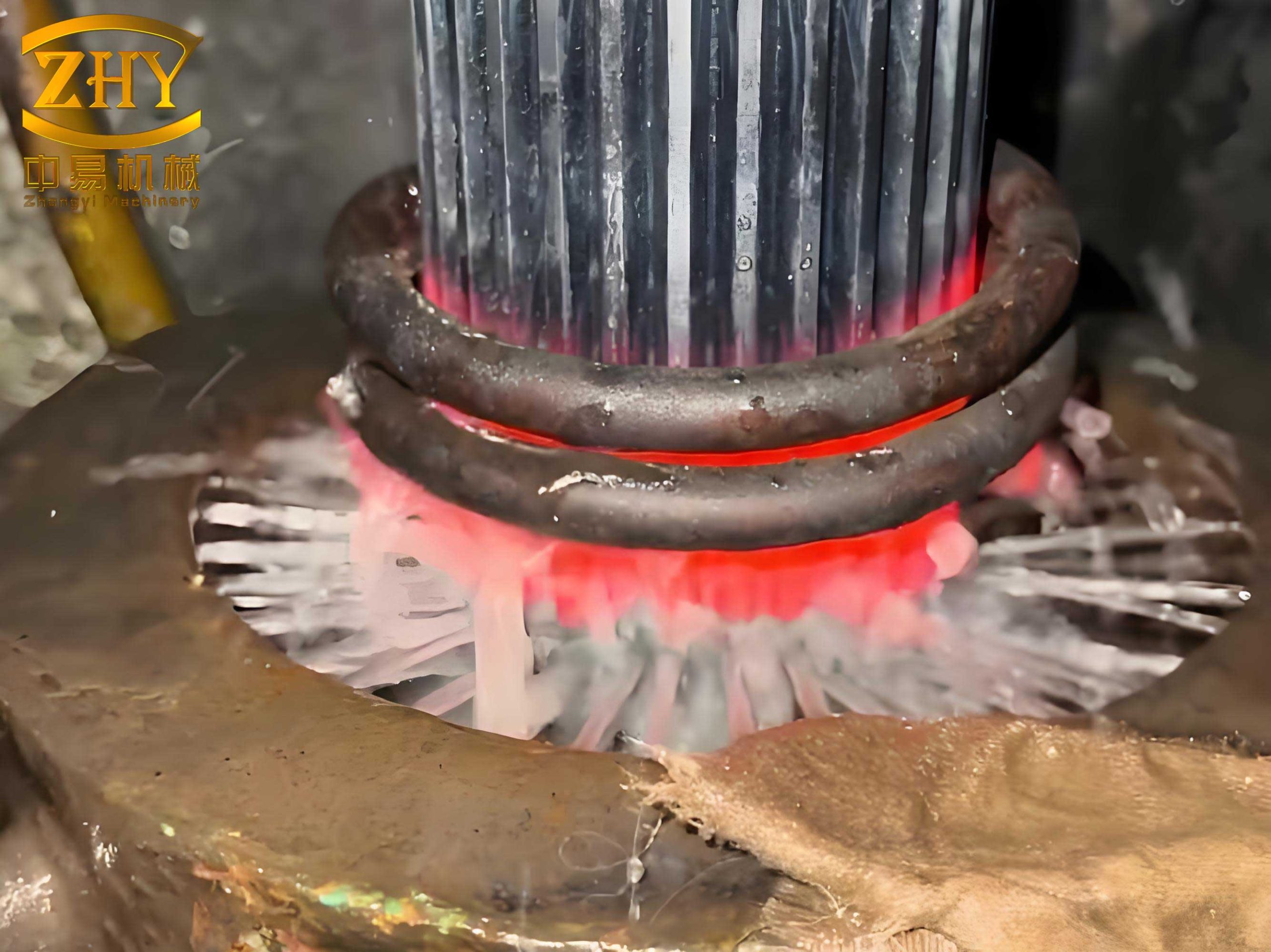
The image above provides a visual representation of typical heat treatment defects stemming from distortion and stress, underscoring the practical reality of these theoretical mechanisms.
| Mechanism | Primary Cause | Typical Manifestation | Governing Factors |
|---|---|---|---|
| Geometric Shape Distortion | Plastic yielding due to unbalanced thermal and transformation stresses. | Bending, bowing, twisting, out-of-roundness. | Cooling rate gradients, part geometry, material hardenability. |
| Volumetric Size Change | Net change in specific volume from phase transformations. | Uniform expansion or contraction; can cause size drift. | Carbon content, retained austenite, final microstructure mix. |
2. A Holistic View of Influencing Factors
Contrary to common practice, the root causes of final distortion are not seeded solely during quenching. The heat treatment process merely activates and reveals the cumulative latent stresses and asymmetries implanted throughout the manufacturing chain. Therefore, effective management of heat treatment defects requires scrutiny of every preceding step.
| Factor Category | Specific Elements | Impact on Distortion |
|---|---|---|
| Material Factors | Chemical Composition (Hardenability) | Determines Ms temperature, transformation kinetics, and susceptibility to stress. Steels like SAE 8620RH have carefully controlled bands to minimize variability. |
| Material Anisotropy (Forging Flow Lines) | Directional properties from forging can lead to non-uniform transformation and stress relief, causing directional distortion patterns. | |
| Initial Microstructure (Post Normalizing) | A uniform, fine-grained ferrite-pearlite structure provides a consistent starting point, reducing unpredictable transformation behavior. | |
| Design & Geometry Factors | Part Symmetry | Asymmetric parts (e.g., one end with a small bore, the other with a large internal spline) inherently cool and transform non-uniformly, creating a predictable distortion “trend.” |
| Section Thickness Variations | Thin walls cool faster than thick hubs, creating large thermal gradients and stress concentrations. | |
| Stress Concentration Features (Sharp corners, keyways) | Act as initiation sites for stress-induced distortion and even quenching cracks. | |
| Manufacturing Process Factors | Forging: Temperature, deformation, cooling rate. | Introduces residual stresses, grain flow orientation, and potential banding. Poorly controlled forging is a major source of latent stress. |
| Normalizing/Annealing: Temperature, time, cooling. | Primary method for homogenizing microstructure and relieving forging/machining stresses before final machining. | |
| Machining: Cutting parameters, sequence, clamping. | Introduces surface and sub-surface residual stresses (tensile or compressive). Unbalanced clamping or aggressive cuts can severely warp a part before it even reaches the furnace. | |
| Pre-Heat Treatment Stress Relief: (e.g., Low-Temp Anneal) | Critical but often omitted step to relieve machining stresses immediately before carburizing, stabilizing the part geometry. | |
| Heat Treatment Process Factors | Furnace Temperature Uniformity | Temperature gradients during heating and carburizing can cause uneven austenitization and case depth. |
| Quenching Medium & Agitation | Oil temperature, agitation speed/profile are the most direct controls over cooling gradients and the severity of thermal shock. | |
| Part Fixturing and Orientation in Quench | How the part enters the oil (e.g., vertical vs. horizontal) drastically affects flow uniformity and cooling symmetry. |
3. Case Study: Rectifying Distortion in a High-Volume Gear
We now examine a real-world scenario where a sudden spike in a specific heat treatment defect—excessive axial runout—occurred in a high-production gear. The challenge was to salvage a large batch of already-machined components through adjustments in the final heat treatment cycle.
3.1 Part Description and Problem
- Component: Large diameter (approx. Ø219.3 mm), thin-web automotive gear with an asymmetric design: one side (A) featured a large internal spline, the other side (B) a smaller bore.
- Material: SAE 8620RH (modified).
- Specification: Case depth: 0.84-1.34 mm; Surface hardness: 58-63 HRC.
- Problem: Post-quench axial runout at the B-face exceeded the 0.06 mm tolerance, causing subsequent gear grinding (crowning and lead angle correction) to fail. The failure rate surged to ~30%.
3.2 Original Heat Treatment Process
The parts were processed in a continuous rotary hearth furnace (42 positions) with integrated pre-oxidation, carburizing, quenching, washing, and tempering. Atmosphere was nitrogen-methanol with acetone enrichment. The original quench oil agitation profile was intense and prolonged, as shown below:
| Parameter | Setting |
|---|---|
| High-Speed Agitation | 1100 rpm for 240 s |
| Low-Speed Agitation | 1100 rpm for the remainder (total quench time 239 s) |
This profile, while ensuring hardness, provided maximum cooling intensity throughout the martensitic transformation range, likely exacerbating thermal stress.
3.3 Remedial Experiments and Analysis
The goal was to modify the final thermal cycle to compensate for the latent stresses in the batch, without compromising metallurgical properties. Three corrective approaches were tested on sample lots.
Experiment 1: Introduction of a Pre-Carburizing Anneal
A subcritical anneal was performed in a batch tempering furnace: 400°C for 2 hours, furnace cool to 350°C, then air cool. This aimed to relieve machining stresses. After subsequent carburizing and quenching with the original parameters, the average axial runout distortion was a low 0.033 mm. However, sample size was small, and the logistics of an extra off-line furnace operation were cumbersome.
Experiment 2: Optimization of Quench Agitation Parameters
The quenching profile was strategically modified to reduce stress during the martensite formation stage. The ideal quench provides rapid cooling down to just above the Ms point to avoid pearlite, then a slower cooling rate through the martensitic transformation to minimize transformation stress. The parameters were adjusted as follows:
| Parameter | New Setting | Rationale |
|---|---|---|
| High-Speed Agitation Time | 45 s | Ensure rapid cooling through the pearlite “nose” of the CCT diagram. |
| Low-Speed Agitation Speed | 700 rpm | Reduce cooling intensity during the martensite transformation (Ms to Mf) to lower transformation stress. |
| Total Quench Time | 239 s (unchanged) | Maintain overall process time. |
Result: The average distortion decreased from 0.085 mm (original) to 0.057 mm, and the data spread (standard deviation) was tight at 0.015 mm. However, the absolute values were still mostly above the 0.06 mm tolerance limit. This adjustment alone was beneficial but insufficient as a complete remedy for the existing heat treatment defects in this batch.
Experiment 3: Combined Approach – Anneal + Optimized Quench
Based on the promising but incomplete results from Experiments 1 and 2, a synergistic approach was tested.
Variant 3A: Batch Furnace Anneal + Optimized Quench. This yielded excellent results: average distortion of 0.034 mm with a standard deviation of 0.018 mm, and all parts within specification. The downside remained the logistical overhead.
Variant 3B (The Optimized Solution): In-Line Pre-Oxidation Zone Anneal + Optimized Quench. To streamline the process, the subcritical anneal was integrated into the continuous furnace cycle. Parts were held at 400°C for 2 hours within the pre-oxidation zone of the rotary hearth furnace before proceeding to carburizing, followed by the optimized quench.
$$ \text{Total Cycle Time Increase} \approx 3 \text{ hours (creating empty positions)} $$
Result: This method was equally effective as Variant 3A, producing an average distortion of 0.036 mm with a 0.017 mm standard deviation, with all parts in tolerance. It represented the optimal trade-off between corrective efficacy and production feasibility.
| Strategy | Avg. Axial Runout Distortion (mm) | Std. Dev. (mm) | Within Spec? | Production Impact | Conclusion |
|---|---|---|---|---|---|
| Original Process | 0.085 | N/A | No (30% Fail) | Baseline | Unacceptable defect rate. |
| Exp.1: Anneal Only | 0.033 | N/A | Yes (Sample) | High (6h + logistics) | Effective but logistically poor. |
| Exp.2: Optimized Quench Only | 0.057 | 0.015 | Mostly No | None | Improves but insufficient alone. |
| Exp.3A: Batch Anneal + Opt. Quench | 0.034 | 0.018 | Yes | High (6h + logistics) | Technically excellent, practically cumbersome. |
| Exp.3B: In-Line Anneal + Opt. Quench | 0.036 | 0.017 | Yes | Moderate (3h, in-line) | Optimal Solution: Effective & Feasible. |
Final Outcome: Implementing the in-line anneal with optimized quench (Exp. 3B) for the remaining batch successfully reduced the rejection rate from 30% to approximately 6%, demonstrating a powerful method for salvaging parts afflicted by unpredictable heat treatment defects.
4. Toward a Systematic Strategy for Distortion Control
The case study validates that while final heat treatment adjustments can provide crucial remediation, a proactive, system-wide strategy is essential for consistent, long-term control of distortion. This strategy must be vertically integrated across the product lifecycle.
4.1 Pre-Heat Treatment Stabilization
- Mandatory Stress Relief: Implement a low-temperature annealing or stress-relief operation after final machining and before carburizing. This is the single most effective step to eliminate the variable of machining stress. A typical cycle is 550-650°C for 1-2 hours per inch of thickness, followed by slow cooling.
- Material and Forging Consistency: Enforce strict controls on steel cleanliness, hardenability bands, and forging parameters (finish-forging temperature, cooling rate) to ensure a homogeneous and repeatable starting condition.
4.2 Intelligent Heat Treatment Process Design
- Quench Process Engineering: Move beyond fixed agitation settings. Develop quench profiles tailored to the specific part geometry and material. Utilize intensive quenching only until the part’s surface reaches a temperature just above Ms, then drastically reduce cooling rate (e.g., via reduced agitation, higher oil temperature, or interrupted quenching) to allow the martensite transformation to proceed under lower stress gradients. Computational Fluid Dynamics (CFD) can model oil flow and heat transfer for optimization.
- Fixturing and Orientation: Design quenching fixtures that support the part in a way that promotes uniform fluid flow and minimizes gravity-induced sagging during the low-strength austenitic phase.
- Use of Press Quenching or Die Quenching: For critical, high-precision, or highly asymmetric components, quenching in a die that constrains the part to its nominal shape can virtually eliminate geometric distortion, though at a higher tooling cost.
4.3 Data-Driven Process Control and Feedback
- Statistical Process Control (SPC): Continuously monitor key distortion parameters (runout, size change, gear profile) and correlate them with upstream process variables (forging lot, machining batch, furnace loads). This helps identify drift and root causes early.
- Digital Twins and Simulation: Develop finite element method (FEM) models that simulate temperature fields, phase transformations, and stress/strain evolution during quenching for new part designs. This predictive capability allows for “virtual prototyping” of the heat treatment process, identifying potential heat treatment defects before tooling is even cut.
The generalized workflow for managing distortion can be summarized as a continuous loop:
$$ \text{Design} \rightarrow \text{Material Selection} \rightarrow \text{Forging Control} \rightarrow \text{Machining Strategy} \rightarrow \text{Pre-HT Stress Relief} \rightarrow \text{Optimized Quench Design} \rightarrow \text{Measurement & Feedback} $$
Each arrow in this chain represents a critical control point where decisions impact the final dimensional outcome.
5. Conclusion
Heat treatment distortion is not a solitary heat treatment defect to be solved in the furnace alone. It is the cumulative result of interactions between material history, part geometry, and every thermal and mechanical process it undergoes. The successful remediation of the gear distortion case underscores two vital principles: first, that introducing a stabilizing anneal to relieve prior stresses can be remarkably effective; and second, that quenching parameters must be intelligently designed to manage cooling through the martensitic transformation, not just to achieve hardness.
A sustainable solution, however, requires breaking down organizational silos. Collaboration between product design, forging, machining, and heat treatment engineering is non-negotiable. By adopting a holistic, process-chain-oriented approach—incorporating mandatory stress relief, optimized quenching engineering, and data-driven feedback loops—manufacturers can transform distortion from an unpredictable nuisance into a predictable and manageable characteristic. This shift is essential for advancing the quality, reliability, and cost-effectiveness of high-performance automotive components in an increasingly competitive landscape.