1. Model of helical gears
1.1 Model of helical gear transmission system
| Parameters | Driving gear parameter values | Driven gear parameter values |
| Number of teeth | 23 | 93 |
| Normal modulus | 1.93 | 1.93 |
| Pressure angle/(°) | 16.0 | 16.0 |
| Spiral angle/(°) | 25.6 | 25.6 |
| Displacement coefficient | 0.4300 | 0.0387 |
| Tooth width/mm | 42.0 | 46.5 |
| Center distance/mm | 125 | 125 |
| Accuracy level | 8 | 8 |
| Input speed 1/(r · min ^ -1) | 20000 | 20000 |
| Input speed 2/(r · min ^ -1) | 3500 | 3500 |
| Input torque 1/(N · m) | 19.5 | 19.5 |
| Input torque 2/(N · m) | 111.4 | 111.4 |
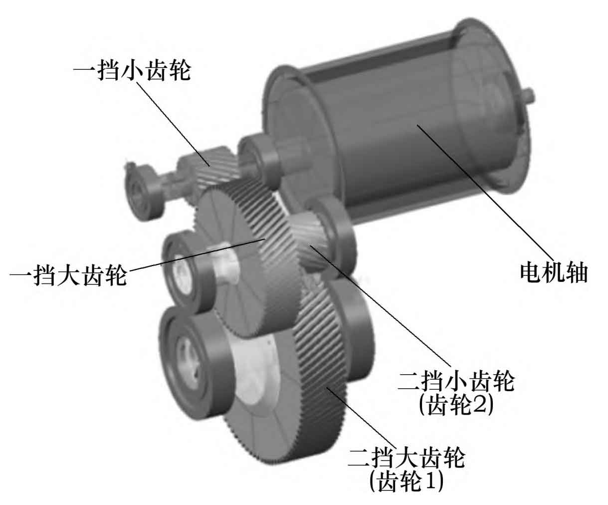
Using the SABR module in Ricardo software, establish a model of the secondary reduction helical gear transmission system for a pure electric vehicle. Based on the load spectrum shown in Table 1 and the relevant parameters of the secondary reduction helical gear, as well as the relevant helical gear material, machining accuracy, and heat treatment, obtain the required standard helical involute helical gear pair model. Among them, the shaft and bearings are selected and established through a standard library. The structural model of the transmission system in this article is shown in Figure 1.
1.2 Micro modification plan for helical gears
| Shape modification parameters | High speed cultivation volume/ μm driving gear | High speed cultivation volume/ μm Driven gear | Low speed cultivation volume/ μm driving gear | Low speed cultivation volume/ μm Driven gear |
| Tooth drum shape | 2 | 2 | 6 | 6 |
| Tooth end oblique modification amount | -6 | -4 | -6 | -6 |
| Linear modification amount of tooth top | 2 | 2 | 7 | 7 |
| Tooth profile bulge quantity | 3 | 3 | 8 | 8 |
| Pressure angle correction amount | 2 | -2 | 7 | -7 |
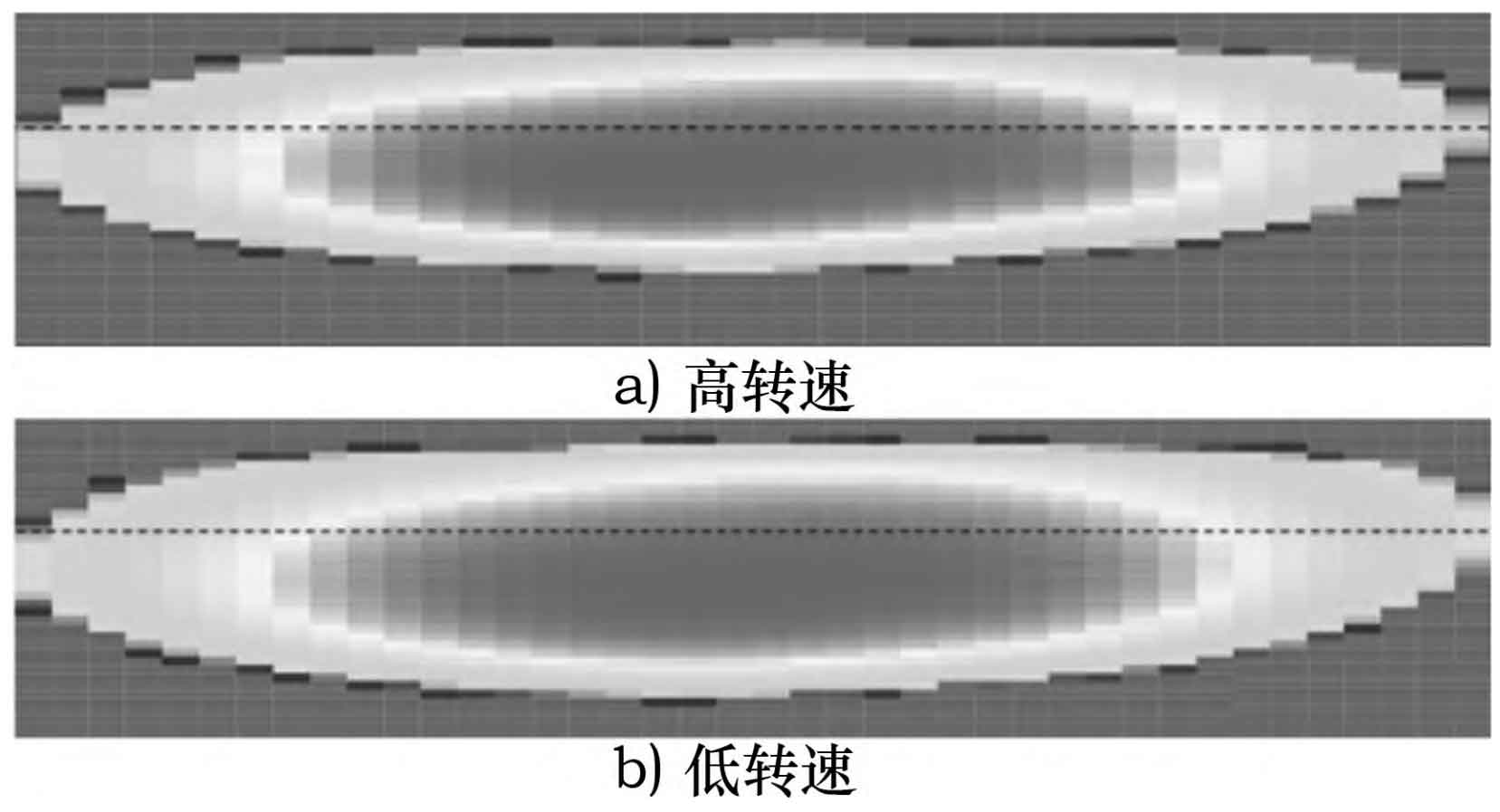
Using the same amount of modification for the helical gear drive surface and reverse drag surface, a comprehensive modification method for tooth direction, tooth profile, and pressure angle is adopted to determine a set of near optimal modification schemes. The specific modification scheme parameters of the helical gear pair under high and low speed are shown in Table 2, and the contact spot of the modified helical gear is shown in Figure 2. It can be seen that the contact stress on the tooth surface after modification is distributed at the center position of the helical gear.
1.3 Tooth surface mesh model and partitioning method
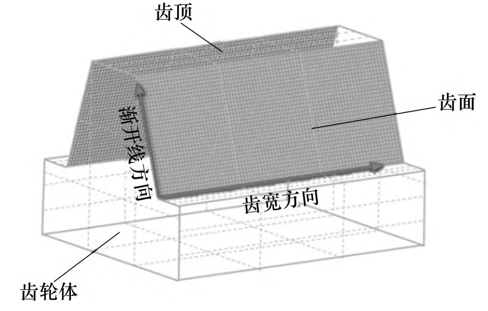
The division method and number of mesh on the tooth surface have a significant impact on the reliability of simulation results. A reasonable number of grids and partitioning methods play an important role in improving the accuracy and computational efficiency of simulation results. The mesh model of the helical gear tooth surface is shown in Figure 3. This study uses the SABR ⁃ Gear module in Ricardo software, with a unit grid size as a step, starting from 20 grids along the tooth width and involute direction, until the maximum tooth surface contact stress, peak to peak transmission error, and tooth surface contact spot no longer fluctuate significantly with changes in the number of grids along the involute and involute directions, At this point, the default has reached the optimal number of grids for simulation calculation accuracy.
2. Theoretical calculations
2.1 Dynamic model of helical gear pair
Figure 4 shows the dynamic model of an 8-degree-of-freedom parallel axis helical gear transmission system established using the centralized parameter method.
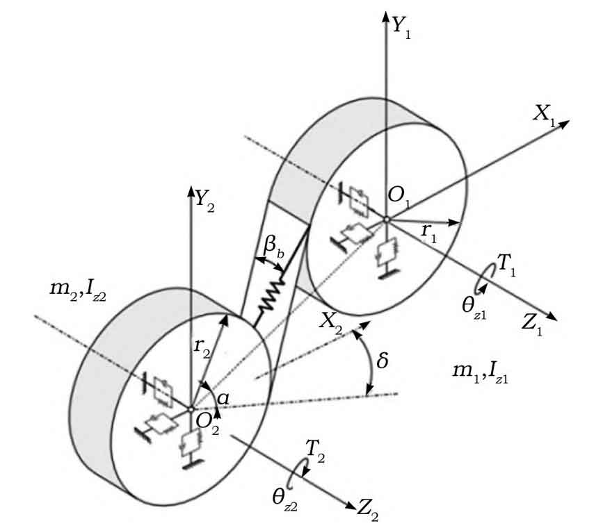
In Figure 4, T1 and T2 represent the load torque and input torque, respectively; R1 and r2 are the base radius of the driven gear and the driving gear, respectively; M1 and m2 are the masses of the driven gear and the driving gear, respectively; Iz1 and Iz2 are the rotational inertia of the driven gear and the driving gear around the Z-axis, respectively; β B is the meshing helix angle; α Is the pressure angle; δ Is the tilt angle of the X-axis; θ Z1 θ Z2 represents the angle of rotation of the driven gear and the driving gear around the Z-axis, respectively.
The dynamic equation of the helical gear pair is:
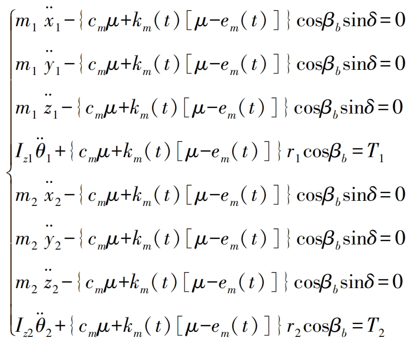
In the formula: t is the meshing time of the helical gear; θ 2 θ 1. The rotation angles of the main and driven gears respectively; θ 2 θ 1. The rotational angular acceleration of the main and driven gears, respectively; The vibration acceleration of the main and driven gears in the X, Y, and Z axis directions, respectively, for x-2, y-2, z-2, x-1, y-1, and z-1; Cm is the meshing damping of the helical gear pair; Km (t) is the time-varying mesh stiffness; Em (t) is the comprehensive meshing error considering helical gear modification and helical gear meshing misalignment; μ The relative displacement of the helical gear pair along the meshing line.
Considering the meshing impact of helical gears, the motion equation of the helical gear pair in matrix form is:

In the formula: M is the mass matrix; C is the damping matrix; K (t) is the stiffness matrix; F is the equivalent load vector; Q (t) is the displacement vector; Q · (t) is the velocity vector; Q (t) is the acceleration vector; E (t) is the static transmission error matrix.

In the formula: q is the generalized coordinate system of the system; X2, y2, z2, x1, y1, z1 are the vibration displacements of the driving gear and the driven gear in the X, Y, and Z directions.
2.2 Calculation of tooth contact stress
The calculation method of tooth contact stress theory is to solve the extreme value of helical gear tooth contact stress by combining Hertz contact theory and helical gear meshing theory.
Hertz contact theory suggests that the maximum contact stress on the tooth surface usually occurs in the area below the indexing circle and the indexing circle of the driving gear, and the maximum contact stress on the tooth surface σ The calculation formula for H is:
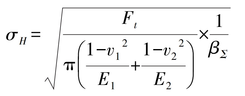
In the formula: βΣ The comprehensive curvature radius at the peak stress position; Ft is the circumferential force; V1 and v2 are the circumferential velocities of the driven gear and the driving gear, respectively; E1 and E2 are the elastic moduli of the driven gear and the driving gear, respectively.
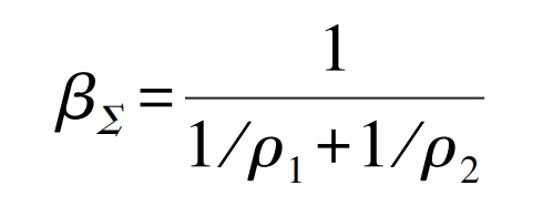
In the formula: ρ 1 ρ 2 are the curvature radii of the peak stress positions of the driven gear and the driving gear, respectively.
2.3 Theoretical Calculation of Transmission Error
Transmission Error (TE) is the deviation between the actual meshing position of the tooth profile on the driven gear and the ideal position under ideal conditions, measured from the direction of the meshing line. The schematic diagram of the transmission error is shown in Figure 5, and the calculation formula for the transmission error TE is:
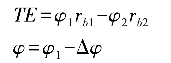
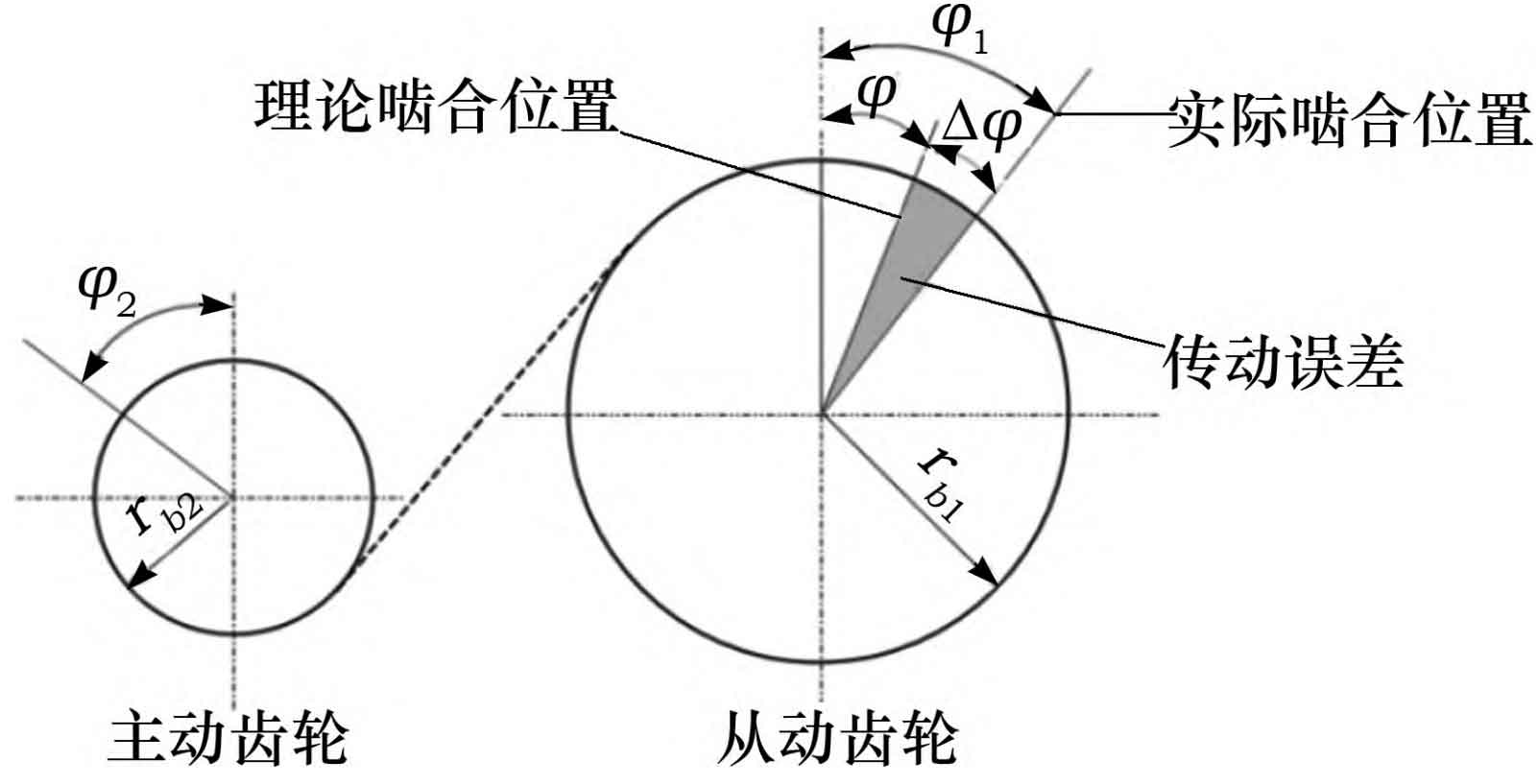
In the formula, rb1 and rb2 are the pitch radii of the driven gear and the driving gear, respectively; φ 1 is the actual rotation angle of the driven gear; φ 2 is the actual rotation angle of the driving gear; φ Theoretical angle of driven gear; Δφ The angle deviation value caused by transmission error.
