
Throughout my work in mechanical design, I have frequently encountered the need to analyze gear transmissions. Straight spur gears are among the most widely used mechanical components, yet their complex tooth geometry makes traditional calculation methods insufficient for accurately determining stress and strain distributions. In this study, I present a comprehensive approach to modeling and finite element analysis of straight spur gears using SolidWorks. I focus on a pair of meshing straight spur gears from a lathe headstock—specifically the gears on shaft I and shaft II. By combining parametric modeling techniques with simulation, I aim to verify the structural integrity of these straight spur gears under typical operating conditions.
Before diving into the modeling process, it is essential to understand the significance of straight spur gears in power transmission. They are simple, efficient, and widely used in machine tools, automotive gearboxes, and industrial machinery. However, the contact stresses at the tooth flanks and the bending stresses at the root are critical failure points. Finite element analysis (FEA) offers a powerful tool to predict these stresses, provided that a precise three-dimensional model of the straight spur gear is available. In the following sections, I describe two alternative modeling methods and then perform a static structural analysis on one of the gears.
Gear Modeling Methods
I adopted two distinct approaches to create accurate solid models of straight spur gears: (1) combined CAXA and SolidWorks modeling, and (2) formula-driven curve method within SolidWorks. Both methods enable the generation of precise involute profiles essential for straight spur gear geometry. The gear parameters used in this study are listed in Table 1.
| Gear | Module (mm) | Pressure Angle (°) | Tooth Width (mm) | Elastic Modulus (MPa) | Poisson’s Ratio |
|---|---|---|---|---|---|
| Large gear on shaft I | 3 | 20 | 25 | 2.1×10⁵ | 0.28 |
| Small gear on shaft II | 3 | 20 | 20 | 2.1×10⁵ | 0.28 |
The large gear has 51 teeth and the small gear has 43 teeth, with a center distance of 141 mm. Both are made of 45 steel, a common material for straight spur gears. Now, let me detail each modeling approach.
Method 1: CAXA and SolidWorks Combined Modeling (Example – Large Straight Spur Gear on Shaft I)
First, I used CAXA’s built-in gear design module to generate a 2D profile of the straight spur gear. By entering the parameters from Table 1 into the involute tooth profile menu, CAXA produced an accurate 2D outline of the large gear tooth. I saved this drawing as a DXF/DWG file (e.g., clk.dwg). Next, I opened this file in SolidWorks using the “Import to New Part” option. The 2D geometry was then extruded to a depth of 25 mm to create the gear blank. Finally, I added the central bore and keyway features to complete the three-dimensional solid model of the large straight spur gear. This method is straightforward and leverages the specialized gear design capabilities of CAXA, but it requires an intermediate file transfer.
Method 2: Formula-Driven Curve Method in SolidWorks (Example – Small Straight Spur Gear on Shaft II)
For the small gear, I adopted a more parametric approach using SolidWorks’ equation-driven curve tool. The involute curve of a straight spur gear can be expressed using the following parametric equations, which I derived from the geometry of an involute:
Given a base circle radius \(R_b\) and a rolling angle \(\theta\) (in radians), the coordinates of a point \(K\) on the involute are:
\[
x = R_b \cos \theta + R_b \theta \sin \theta
\]
\[
y = R_b \sin \theta – R_b \theta \cos \theta
\]
I used these equations to drive a 3D curve in SolidWorks. The base circle radius for the small straight spur gear is calculated as \(R_b = \frac{m z \cos \alpha}{2} = \frac{3 \times 43 \times \cos 20^\circ}{2} \approx 60.61\) mm. I set the parameter \(\theta\) to vary from 0 to \(\pi/2\) to cover the involute segment used in the tooth profile. After creating the involute curve, I constructed the complete tooth profile by adding the addendum circle (radius = \(R_a = R_b + m = 64.5\) mm) and dedendum circle (radius = \(R_f = R_b – 1.25m = 56.61\) mm). I then extruded this single tooth to a width of 20 mm. Using the circular pattern feature, I replicated the tooth around the gear axis to obtain all 43 teeth. Finally, I cut the central bore and keyway to finish the small straight spur gear model, as shown in the figure below.
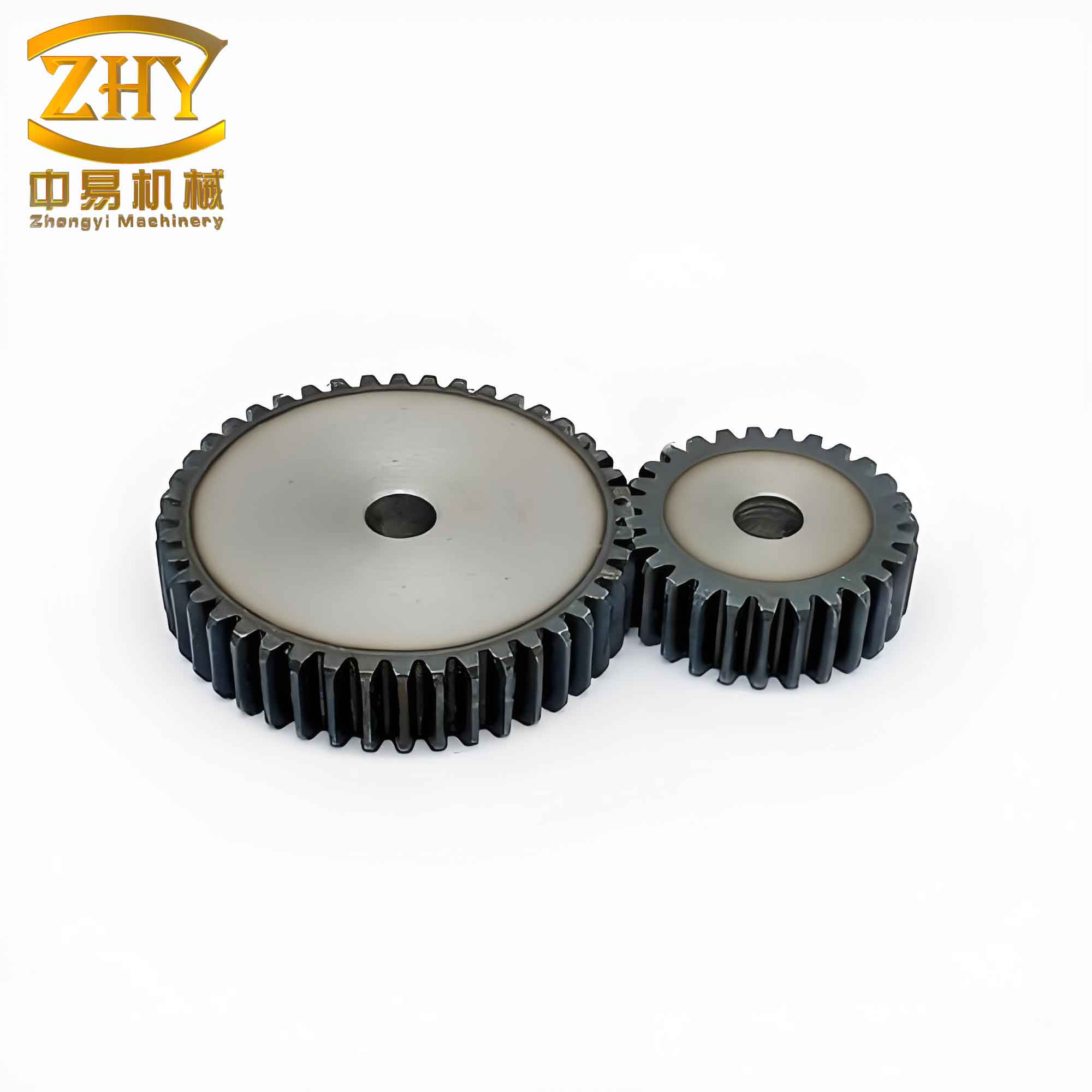
This image illustrates a typical pair of meshing straight spur gears, similar to the ones I modeled. The formula-driven method offers high accuracy and full control over the involute profile, which is crucial for reliable stress analysis. I prefer this method because it stays entirely within SolidWorks and avoids file conversions.
Assembly of the Meshing Straight Spur Gear Pair
To perform a realistic analysis, I needed to assemble the two straight spur gears in a proper meshing configuration. In the SolidWorks assembly environment, I imported both the large gear (shaft I) and the small gear (shaft II). The assembly constraints were applied as follows:
- I fixed the large gear’s axis to pass through the assembly origin, and I aligned its front plane with the assembly’s front plane to define a reference.
- I set the small gear’s axis parallel to the large gear’s axis, and I specified the center distance as \( \frac{m(z_1+z_2)}{2} = \frac{3 \times (51+43)}{2} = 141 \) mm. Additionally, I matched the front planes of both gears and constrained the small gear’s axis to lie on the assembly’s top plane.
- To ensure correct tooth engagement, I aligned a tooth space of the small gear with a tooth of the large gear. This alignment is critical for accurate contact simulation, although for this static analysis I later only analyzed the small gear independently with applied loads.
The resulting assembly provides a visual check of the meshing geometry and can be used for dynamic contact analysis in future work.
Finite Element Analysis
I performed a static structural analysis on the small straight spur gear (shaft II) using the SolidWorks Simulation add-in. The operating conditions were: rotational speed \(n = 300\) rpm and transmitted power \(P = 4\) kW. From these values, I calculated the torque and the corresponding tooth loads.
Loading and Constraints
First, I fixed the inner bore of the small gear—allowing zero displacement in X, Y, and Z as well as zero rotation. This constraint simulates the gear being rigidly mounted on its shaft.
The normal force acting along the line of action of the straight spur gear was decomposed into tangential and radial components. The torque is:
\[
T = 9.55 \times 10^6 \frac{P}{n} = 9.55 \times 10^6 \times \frac{4}{300} \approx 127333.33 \text{ N·mm}
\]
The tangential force (circumferential force) at the pitch circle diameter \(D = m z = 3 \times 43 = 129\) mm is:
\[
F_t = \frac{2T}{D} = \frac{2 \times 127333.33}{129} \approx 1947.16 \text{ N}
\]
The radial force is:
\[
F_r = F_t \tan \alpha = 1947.16 \times \tan 20^\circ \approx 708.71 \text{ N}
\]
For a conservative static analysis, I applied these forces at the tip of a single tooth (at the addendum circle) to simulate the worst-case loading scenario. The normal force magnitude \(F_n = \sqrt{F_t^2 + F_r^2}\) is approximately 2071.5 N.
Mesh and Material
I defined the material as 45 steel with Young’s modulus \(E = 2.1 \times 10^5\) MPa and Poisson’s ratio \(\nu = 0.28\). The gear model was meshed using high-quality solid tetrahedral elements with a fine density at the tooth fillet to capture stress concentration. The final mesh contained 55,393 elements and 83,604 nodes.
Results and Discussion
After solving, I obtained the von Mises stress distribution and total displacement. The results are summarized in Table 2.
| Quantity | Value | Location |
|---|---|---|
| Maximum von Mises stress | 84.538 MPa | Tooth root (fillet region) |
| Maximum displacement | 7.13 × 10⁻³ mm | Tooth tip (addendum edge) |
| Yield strength of 45 steel | 220.594 MPa | — |
The maximum stress of 84.538 MPa occurred at the root of the tooth, which is typical for straight spur gears due to the bending moment. This value is well below the yield strength of 220.594 MPa, indicating a safety factor of about 2.6. The maximum displacement of only 7.13 micrometers at the tooth tip shows that the gear remains within its elastic deformation range. Therefore, the small straight spur gear in this application is structurally safe under the given loading conditions. I also observed that the stress distribution pattern aligns with theoretical expectations for involute straight spur gears.
The accuracy of these results depends heavily on the quality of the gear model. Both modeling methods I employed produced nearly identical geometry, but the formula-driven curve method is more flexible for parametric studies. In practice, I recommend using the equation-driven approach for straight spur gear analysis because it allows easy adjustment of module, tooth number, and pressure angle without relying on external software.
Conclusion
In this work, I successfully demonstrated two efficient methods for modeling straight spur gears in SolidWorks: combined CAXA-SolidWorks and the internal formula-driven curve method. Both techniques generate accurate involute profiles, which are indispensable for reliable finite element analysis. The static structural analysis of the small straight spur gear confirmed that the stresses and deformations are within safe limits, validating the design. The study underscores the importance of precise geometric modeling when performing FEA on straight spur gears. Future work could extend this analysis to dynamic loading, contact stress, and fatigue life prediction. The approach described here provides a robust foundation for engineers who need to evaluate the performance of straight spur gears in various mechanical systems.