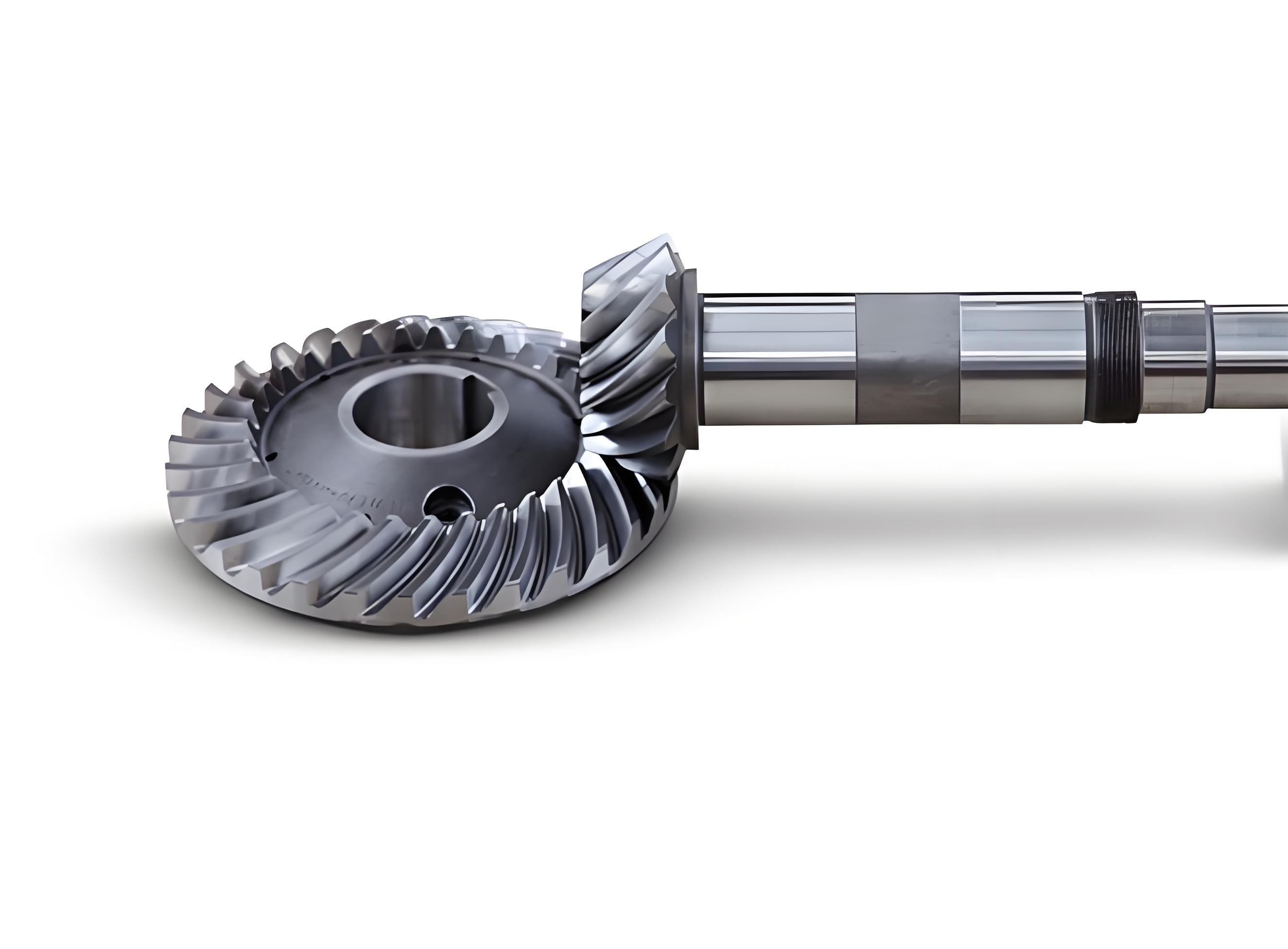
This study investigates the dynamic characteristics of hemispherical spiral bevel gears through a combination of lumped mass modeling, rigid-flexible coupling simulations, and parametric sensitivity analysis. The goal is to optimize gear design parameters for enhanced transmission accuracy, stability, and load capacity.
1. Dynamic Modeling of Spiral Bevel Gear Pairs
The meshing behavior of hemispherical spiral bevel gears is analyzed using spherical involute theory. The tooth surface equation in coordinate system (O₁, x₁, y₁, z₁) is derived as:
$$r^{(1)}(\beta, \phi) = \begin{pmatrix}
\rho [\cos \psi \sin \phi – \sin \psi \cos \phi \sin \gamma_b] \\
-\rho [\sin \psi \sin \phi + \cos \psi \cos \phi \sin \gamma_b] \\
-\rho \cos \phi \cos \gamma_b + L \\
1
\end{pmatrix}$$
Where:
– $\rho$ = cone generatrix length
– $L$ = distance between Os and O₁
– $\gamma_b$ = base cone angle
– $\psi$ = spherical involute development angle

2. Rigid-Flexible Coupling Dynamics
The multi-body dynamics model incorporates both rigid and flexible components:
| Parameter | Value |
|---|---|
| Number of teeth (z) | 12 |
| Normal pressure angle (α) | 20° |
| Module range (mm) | 2.5-12.5 |
| Pitch cone diameter (mm) | 30-150 |
| Material | Structural steel |
| Young’s modulus (GPa) | 210 |
The dynamic equation for the gear system is expressed as:
$$m_i\ddot{X}_i + c_{ix}\dot{X}_i + k_{ix}X_i = -F_x \\
m_i\ddot{Y}_i + c_{iy}\dot{Y}_i + k_{iy}Y_i = -F_y \\
I_i\ddot{\theta}_i = T_i – F_nr_i$$
Where $F_n$ represents the normal meshing force:
$$F_n = k_n \delta_n + c_n \dot{\delta}_n$$
3. Parametric Sensitivity Analysis
The effects of key parameters on gear performance are quantified through response surface analysis:
| Shaft Angle (°) | Pitch Diameter (mm) | ||||||
|---|---|---|---|---|---|---|---|
| 30 | 45 | 60 | 75 | 90 | 120 | 150 | |
| 50 | 0.561 | 0.594 | 0.666 | 0.794 | 0.786 | 1.260 | 3.723 |
| 120 | 1.104 | 1.098 | 1.037 | 0.382 | 0.438 | 0.991 | 2.855 |
The transmission error response surface is modeled as:
$$f(x,y) = 13.23 + 0.1035x – 0.7188y – 8.321 \times 10^{-4}x^2 – 1.555 \times 10^{-3}xy + 0.0123y^2 + 4.375 \times 10^{-6}x^3$$
4. Meshing Stability and Load Capacity
Contact characteristics show strong parameter dependence:
| Diameter (mm) | 50° | 120° |
|---|---|---|
| 30 | -3,650 | -2,247 |
| 150 | -6,592 | -4,118 |
The contact force relationship is expressed as:
$$F_{contact} = 3.875 \times 10^4 – 72.9x – 1452y + 0.4129x^2 + 19.62y^2$$
5. Optimization and Verification
Through multi-objective optimization, the optimal parameters for spiral bevel gears are determined:
| Performance Metric | Optimal Diameter (mm) | Optimal Shaft Angle (°) |
|---|---|---|
| Minimum Transmission Error | 65 | 60 |
| Maximum Stability | 75 | 120 |
| Optimal Load Capacity | 90 | 90 |
The comprehensive optimization formula balances multiple objectives:
$$\min \left[ w_1 \frac{f_{error}}{f_{error}^{max}} + w_2 \frac{f_{contact}}{f_{contact}^{max}} – w_3 \frac{f_{stability}}{f_{stability}^{max}} \right]$$
where $w_1+w_2+w_3=1$ represents weighting factors for different performance requirements.
6. Conclusion
This study establishes a complete methodology for analyzing hemispherical spiral bevel gears through flexible multi-body dynamics. The developed models and simulation results provide critical insights for designing high-performance gear systems with optimal balance between transmission accuracy, operational stability, and load capacity. The parametric relationships revealed through this research enable engineers to make informed decisions when configuring spiral bevel gears for specific applications.
