
Abstract
The modeling and optimization design of assembly errors in the spindle cutter disc component of a gear milling machine. By establishing error models for geometric elements based on small displacement torsors, utilizing Monte Carlo simulation and response surface methodology, and analyzing error transmission properties under series and parallel mating conditions, we propose a tolerance optimization model targeting tolerance cost while constrained by assembly precision reliability and tolerance principles. The application of this method in the spindle cutter disc component of a bevel gear milling machine demonstrates its value in guiding tolerance design.
1. Introduction
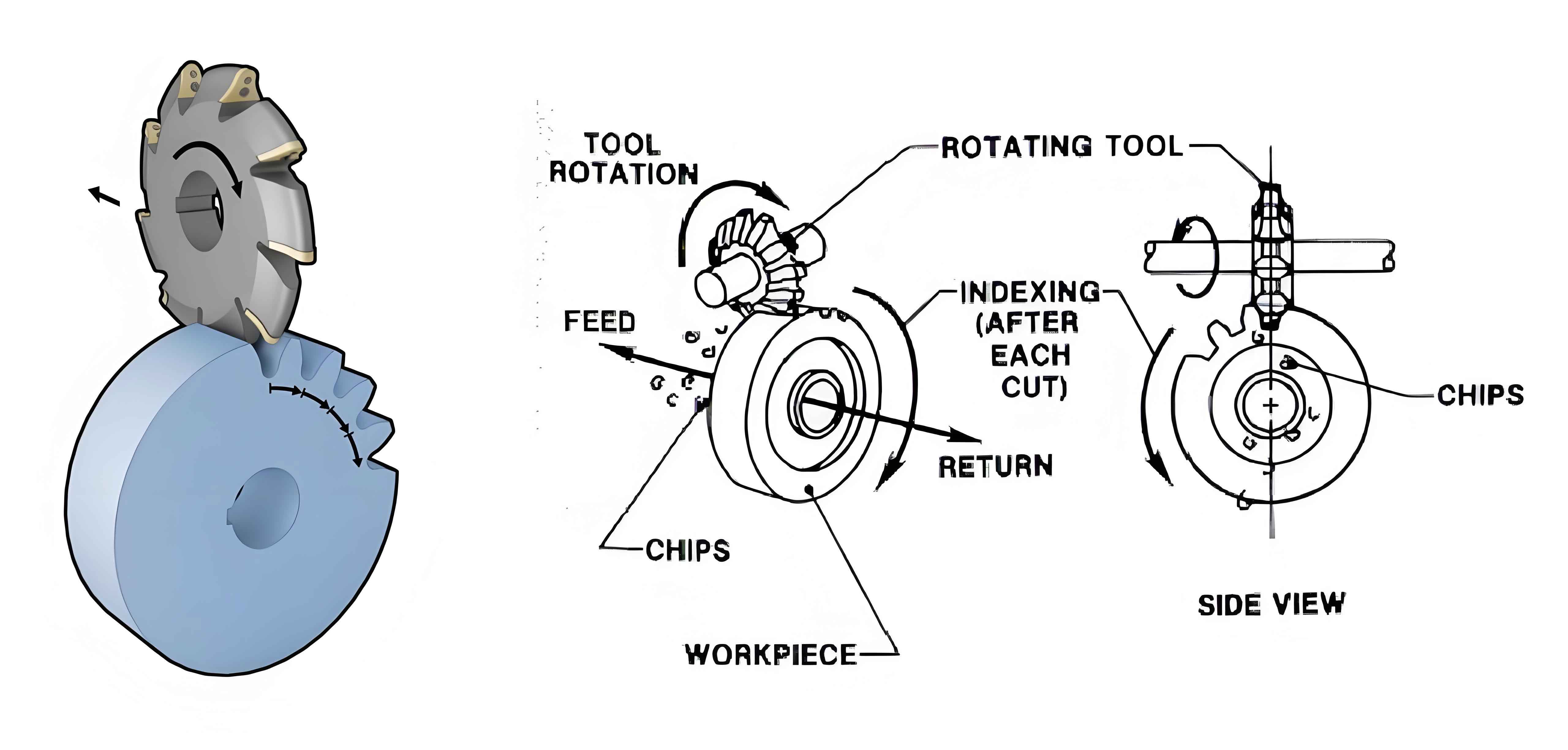
Gear milling machines are critical equipment in the manufacturing industry, and the accuracy of their spindle cutter disc components directly affects the quality of the machined gears. Assembly errors in these components can lead to deviations in gear tooth profiles, affecting gear performance and service life. Therefore, it is essential to study assembly error modeling and optimization design to improve the accuracy and reliability of gear milling machines.
2. Literature Review
Many scholars have conducted extensive research on tolerance modeling and optimization. Zheng Zhongpeng et al. [1] established a spatial geometric error model for a turn-milling composite machine tool based on multi-body system kinematics theory. Yu Zhimin [2] established tolerance models for planar size tolerance, flatness tolerance, axial straightness tolerance, and cylindricity tolerance based on the small displacement torsor method and analyzed error variations. Lv Cheng et al. [3-4] established error models for plane mating surfaces and cylindrical mating surfaces and analyzed the transmission properties of parallel mating between planes and cylindrical surfaces. Li Lei et al. [5] optimized the geometric accuracy of the spindle axis of a vertical machining center based on a multi-objective genetic algorithm and verified the optimization results. Mu X et al. [6] conducted assembly error optimization design with manufacturing and assembly process total cost as the objective and assembly accuracy requirements as constraints.
However, these studies did not involve tolerance modeling of conical surfaces, assembly errors between planes and conical surfaces, and most did not consider reliability in tolerance optimization. Therefore, this paper focuses on geometric element error analysis of conical surfaces, establishes an error model for parallel mating between cones and planes, establishes an assembly accuracy model and reliability model, and proposes a tolerance optimization model combining tolerance cost, assembly precision reliability, and tolerance principles.
3. Modeling of Mating Surface Errors
The mating surfaces of the spindle cutter disc component mainly include conical mating surfaces, cylindrical mating surfaces, and planar mating surfaces. The error formation mechanism of conical mating surfaces is similar to that of cylindrical surfaces, which can be regarded as the positional and orientational variation of the ideal axis of a cone hole relative to the ideal axis of a cone shaft.
Table 1: Error Parameters of Mating Surfaces
| Mating Surface | Geometric Element | Tolerance Range |
|---|---|---|
| Cylindrical Mating Surface D1 | Inner Cylindrical Hole Size Tolerance T1 | [0.01, 0.03] |
| Cylindricity Tolerance T2 | [0.001, 0.01] | |
| Axial Position Tolerance T3 | [0.003, 0.012] | |
| Outer Cylindrical Surface Axial Straightness Tolerance T4 | [0.001, 0.01] | |
| Cylindricity Tolerance T5 | [0.001, 0.01] | |
| Shaft Size Tolerance T6 | [0.01, 0.03] | |
| Conical Mating Surface D2 & Planar Mating Surface D3 | Spindle Outer Cone Size Tolerance T7 | [0.002, 0.02] |
| Cutter Inner Cone Size Tolerance T8 | [0.002, 0.02] | |
| Axial Position Tolerance T3 | [0.003, 0.012] | |
| Planar Mating Surface D3 | Cutter Plane Size Tolerance T9 | [0.005, 0.02] |
| Perpendicularity Tolerance T10 | [0.001, 0.01] |
4. Error Transmission Model and Tolerance Optimization
4.1 Error Transmission Model
The spindle cutter disc component of the gear milling machine consists of a tool, spindle, and housing. The assembly error accumulates from the housing to the spindle and finally transfers to the cutter, resulting in displacement assembly errors in various directions.
4.1.1 Actual Error Transmission Calculation for Parallel Mating Surfaces
The spindle and the cutter cone form a conical mating surface, and the right end face of the spindle and the left end face of the cutter form a planar mating surface. The error calculation steps are as follows:
- Determine the assembly positioning sequence and identify the high-level mating surface.
- Solve the error transmission attributes.
- Solve the actual error transmission attributes of the two mating surfaces.
- Solve the errors of the mating surfaces.
- After assembly, check for interference and adjust the pose to achieve assembly.
4.1.2 Error Transmission Model of the Spindle Cutter Disc Component
Based on the composition of the mating surfaces, with the cylindrical surface as the starting point of error transmission and the cutter plane as the accuracy output plane, the error transmission model of the spindle cutter disc component is established.
4.2 Experimental Validation
Laser scanning experiments were conducted on a gear milling machine to obtain point cloud data of the spindle cutter disc component. The experimental acquisition interface.
Based on the point cloud data of the spindle cutter disc component after scanning, the local point cloud of the cutter was extracted. The RANSAC algorithm was used to fit a circle.
The experimental and theoretical comparison results in the x and y directions are shown in Table 2. The assembly errors in both directions of the spindle cutter disc component are less than the maximum values simulated by the assembly error transmission model, proving the correctness of the established assembly error transmission model.
Table 2: Comparison of Experimental and Theoretical Assembly Errors
| Direction | Experimental Error (mm) | Theoretical Error (mm) |
|---|---|---|
| x | 0.0180 | 0.052 |
| y | 0.0056 | 0.043 |
4.3 Establishment of Tolerance Optimization Model
A tolerance optimization model was established with the processing cost of the spindle cutter disc component as the optimization objective function, dimensional tolerance, form tolerance, and positional tolerance as optimization variables, and assembly precision reliability and tolerance principles as constraints.
The assembly error precision ≤0.035 has a reliability probability of 97.71%. Combined with the tolerance optimization allocation model, the tolerance optimization model for the assembly accuracy of the spindle cutter disc component is established.
4.4 Result Analysis
Table 3: Original and Optimized Tolerance Values
| Tolerance Name | Original Tolerance (mm) | Optimized Tolerance (mm) |
|---|---|---|
| T1 | 0.022 | 0.024 |
| T2 | 0.003 | 0.006 |
| T3 | 0.005 | 0.008 |
| T4 | 0.003 | 0.007 |
| T5 | 0.003 | 0.005 |
| T6 | 0.015 | 0.013 |
| T7 | 0.004 | 0.006 |
| T8 | 0.004 | 0.006 |
| T9 | 0.010 | 0.015 |
| T10 | 0.003 | 0.005 |
The optimized processing cost is 105.41 yuan, a decrease of 8.36% compared to the original processing cost of 115.03 yuan. The assembly precision reliability remains above 97%. Therefore, the particle swarm tolerance optimization method proposed in this paper can reduce processing costs while ensuring assembly accuracy and reliability.
5. Conclusion
Based on the small displacement torsor method, error variation models for geometric elements, particularly conical surfaces, were successfully established. Utilizing Monte Carlo simulation, the actual variation range of the torsor parameters was determined. Furthermore, the relationship between the actual variation interval bandwidth of error components and their corresponding functions was established through response surface methodology. These foundational elements paved the way for modeling assembly error transmission and optimizing tolerances.
The assembly error transmission was primarily analyzed with mating surfaces serving as nodes. Specific focus was given to error calculation methods for conical surfaces. The error transmission mechanisms for both series and parallel mating configurations were investigated, and the actual error transmission properties of the mating surfaces were analyzed in detail.
An optimization model for tolerances was proposed, aiming to minimize cost while ensuring assembly accuracy reliability and adhering to tolerance selection principles. This model served as a guideline for tolerance design and optimization.
Through case studies on the spindle cutter head assembly of a bevel gear milling machine, the effectiveness of the proposed methods was validated. Results indicated a significant reduction in processing costs by 8.36% compared to the original tolerance settings, while maintaining an assembly accuracy reliability of over 97%. This demonstrates the practical value and effectiveness of the proposed error modeling and tolerance optimization approach.
In summary, this paper contributes to the field by providing a comprehensive framework for modeling and optimizing assembly errors in mechanical components, particularly those involving conical surfaces. The findings not only advance the theoretical understanding of assembly error transmission but also offer practical solutions for tolerance design and cost reduction in manufacturing processes.