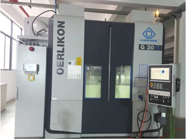
In gear milling operations, cumulative machining errors critically impact assembly precision. This necessitates geometric feature analysis and assembly error modeling to optimize tolerance design. We present a methodology integrating small displacement torsors (SDT), Monte Carlo simulation, response surface methods, and reliability-based optimization for bevel gear milling machine spindle cutter disc assemblies.

1. Geometric Feature Error Modeling Using Small Displacement Torsors
SDT represents geometric deviations as a vector $\mathbf{D} = (\alpha, \beta, \delta, u, v, \omega)$, where $\alpha, \beta, \delta$ denote rotational errors about $x,y,z$-axes, and $u, v, \omega$ denote translational errors. For conical surfaces common in gear milling, the tolerance zone is bounded by:
$$
\begin{cases}
2ny + z = 2n(R + T_U) \\
2ny + z = 2n(R – T_L)
\end{cases}
$$
where $R$ = nominal radius, $T_U/T_L$ = upper/lower deviations, $n$ = taper ratio. SDT parameters satisfy:
$$
-\frac{Th}{\sqrt{\left[h^2 + (T – h/2n)^2\right]\left[h^2 + (h/2n)^2\right]}} \leq \alpha \leq \frac{Th}{\sqrt{\left[h^2 + (T + h/2n)^2\right]\left[h^2 + (h/2n)^2\right]}}
$$
$$
-T_L \leq v \leq T_U
$$
Table 1 summarizes SDT constraints for key geometric features in gear milling systems.
| Feature | Error Constraints |
|---|---|
| Plane | $$ -\frac{T}{2c} \leq \alpha \leq \frac{T}{2c} \\ -\frac{T}{2b} \leq \beta \leq \frac{T}{2b} \\ -T_L \leq \omega \leq T_U $$ |
| Cylinder | $$ -\frac{T + t}{2h} \leq \alpha \leq \frac{T + t}{2h} \\ -T_L – t \leq v \leq T_U $$ |
| Cone | $$ R – T_L – \frac{h}{2n} \leq \frac{(1+2n\alpha)[z-2n(R-T_L)]}{\alpha-2n} + v – 2n(R-T_L)\alpha \leq R + T_U $$ |
2. Actual Variation Bandwidth via Monte Carlo and Response Surface Methods
Monte Carlo simulation generates random SDT parameters ($N_g=10,000$ samples) adhering to tolerance constraints. For normally distributed errors ($6\sigma$ range):
$$
\hat{\mu} = \frac{1}{2N_g} \sum_{i=1}^{2N_g} k_i, \quad \hat{\sigma}^2 = \frac{1}{2N_g} \sum_{i=1}^{2N_g} (k_i – \hat{\mu})^2
$$
where $k = \alpha, \beta, \delta, u, v, \omega$. Actual bandwidth $D_i$ is:
$$
D_i = \frac{6\hat{\sigma}_i}{G} \quad (G=1 \text{ for normal distribution})
$$
Response surface methodology establishes $D_i = f(T_j)$:
$$
D_j = c_0 + c_1T_1 + c_2T_2 + c_3T_1^2 + c_4T_1T_2 + c_5T_2^2 \quad (j=\alpha,\beta,u,v)
$$
Accuracy is validated using R-squared ($R_j^2 > 0.9$):
$$
R_j^2 = \frac{\sum_{i=1}^{n_2} (\hat{D}_{ij} – \bar{D}_j)^2}{\sum_{i=1}^{n_2} (D_{ij} – \bar{D}_j)^2}
$$
3. Mating Surface Error Modeling in Gear Milling
For conical mating surfaces (Figure 3), error propagation is:
$$
\alpha_{34} = \alpha_{33′} + \alpha_{3’4′} + \alpha_{4’4}, \quad u_{34} = u_{33′} + u_{3’4′} + u_{4’4}
$$
where subscripts denote ideal-to-actual axis transitions. The homogenous transformation matrix is:
$$
\mathbf{M}_{34} = \begin{bmatrix}
1 & 0 & \beta_{34} & u_{34} \\
0 & 1 & -\alpha_{34} & v_{34} \\
-\beta_{34} & \alpha_{34} & 1 & 0 \\
0 & 0 & 0 & 1
\end{bmatrix}
$$
Error transmission properties differ for series/parallel mating. For parallel cone-plane mating in gear milling:
$$
\mathbf{A}_{pg} = (\alpha, \beta, 0, u, v, \omega), \quad \mathbf{PS} = \{\alpha, \beta, u, v, \omega\}, \quad \mathbf{PW} = \emptyset
$$
4. Reliability Analysis and Tolerance Optimization
Assembly reliability $R(\mathbf{T})$ is evaluated via Monte Carlo simulation (Figure 4). The limit state function $g(\mathbf{T}) = r – R(\mathbf{T})$ defines failure ($g(\mathbf{T}) > 0$). Tolerance optimization minimizes cost $C(\mathbf{T})$ subject to reliability and tolerance hierarchy constraints:
$$
\min C(\mathbf{T}) = \sum_{i} \left( a_i e^{-b_i T_i} + \frac{c_i T_i}{d_i T_i + e_i} \right)
$$
$$
\text{s.t.} \quad r – R(\mathbf{T}) \leq 0, \quad T_{jS} > T_{jP} > T_{jD} \quad \forall j
$$
5. Case Study: Bevel Gear Milling Machine Spindle Cutter Disc
The assembly (Figure 5) features cylindrical ($a,b$), conical ($c,d$), and planar ($e,f$) mating surfaces. Error propagation from housing to cutter disc is modeled as:
$$
\mathbf{M} = \mathbf{E} + \mathbf{E}_{D1} \times \mathbf{M}_{bc} \times \mathbf{E}_{D2} \times \mathbf{M}_{de} \times \mathbf{E}_{D3} \times \mathbf{M}_{fg} – \mathbf{M}_{bc} \times \mathbf{M}_{de} \times \mathbf{M}_{fg}
$$
where $\mathbf{E}_{D1}$, $\mathbf{E}_{D2}$, $\mathbf{E}_{D3}$ are SDT matrices for cylindrical, conical, and planar mating. Response surface equations for conical SDT bandwidths include:
$$
D_\alpha^{cc’} = -6.75 \times 10^{-4} + 0.1223T_7 + 7.15 \times 10^{-5}n – 1.471T_7^2 – 2.76 \times 10^{-4}nT_7 – 1.8 \times 10^{-6}n^2
$$
Monte Carlo results (Figures 7–9) show maximum assembly errors of $0.052$ mm ($x$), $0.043$ mm ($y$), and $0.009$ mm ($z$). Experimental validation using laser scanning confirmed model accuracy (Table 5).
| Direction | Simulated Max (mm) | Experimental (mm) |
|---|---|---|
| $x$ | 0.052 | 0.018 |
| $y$ | 0.043 | 0.0056 |
Particle swarm optimization ($w=0.8$, $c_1=c_2=0.5$, population=500) yielded:
| Tolerance | Initial (mm) | Optimized (mm) |
|---|---|---|
| $T_1$ | 0.022 | 0.024 |
| $T_2$ | 0.003 | 0.006 |
| $T_3$ | 0.005 | 0.008 |
| $T_4$ | 0.003 | 0.007 |
| $T_5$ | 0.003 | 0.005 |
| $T_6$ | 0.015 | 0.013 |
| $T_7$ | 0.004 | 0.006 |
| $T_8$ | 0.004 | 0.006 |
| $T_9$ | 0.010 | 0.015 |
| $T_{10}$ | 0.003 | 0.005 |
| $T_{11}$ | 0.003 | 0.005 |
| $T_{12}$ | 0.010 | 0.015 |
Cost reduced by 8.36% (115.03 → 105.41 units) while maintaining $R(\mathbf{T}) \geq 97\%$.
6. Conclusion
Our methodology enhances gear milling precision through: 1) SDT-based conical feature error modeling, 2) Response surface-linked tolerance-error bandwidths, 3) Parallel mating error transmission analysis, and 4) Reliability-constrained cost optimization. Implemented on a bevel gear milling spindle, it reduced manufacturing costs by 8.36% while ensuring >97% assembly reliability, demonstrating significant value for gear milling tolerance design.
