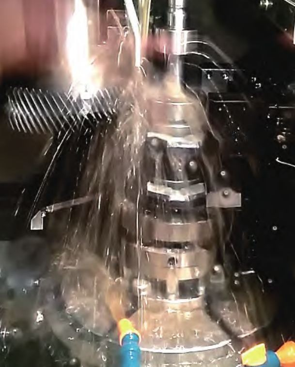
Abstract: The modeling and simulation of helical offset non-orthogonal face gears, aiming to promote their application in various spatial layouts and expand their advantages in the transmission field. The tooth surface equation of the helical offset non-orthogonal face gear is derived, and gear shaping simulation is completed using VERICUT software. The results verify the correctness of the numerical control gear shaping process for helical offset non-orthogonal face gears.

1. Introduction
Face gear transmission, invented by the Fellow Corporation, is a transmission mechanism composed of a cylindrical gear and a bevel gear. It has been successfully applied in robot joint reducers, helicopter power split reducers, differentials in automotive transmission systems, and rear axle drive reducers. Compared to bevel gears, face gear transmissions offer numerous advantages, including lighter weight, smaller size, no axial positioning requirements, high load-bearing capacity, easy replacement, and low noise.
However, the manufacturing difficulties of face gears have limited their application in the transmission field. Existing research has primarily focused on straight-tooth orthogonal face gears, neglecting the more complex and general offset non-orthogonal face gears. To enrich the transmission forms of face gears and meet the requirements of diversified structural layouts in space-constrained transmission systems, this paper designs a face gear incorporating helical teeth, offset, and non-orthogonal parameters.
2. Derivation of Tooth Surface Equation
The tooth surface of the helical offset non-orthogonal face gear is formed by the enveloping action of a helical gear shaper cutter. Unlike straight-tooth face gear shaping, the helical gear shaper cutter axis and the face gear axis are neither parallel nor intersecting, with a mutual angle γm.
2.1 Helical Gear Shaper Cutter Tooth Surface Equation
The tool used for processing helical offset non-orthogonal face gears is an involute helical gear shaper cutter. The position vector Rs of the helical gear shaper cutter tooth surface in the coordinate system Ss can be expressed as:
2.2 Coordinate Systems for Gear Shaping
The gear shaping process of helical offset non-orthogonal face gears adopts the coordinate system. The transformations involve rotating, translating, and re-orienting the coordinate systems to align with the face gear and the gear shaper cutter.
3. MATLAB Simulation of Face Gear Tooth Surface
Through theoretical derivation, the tooth surface equation of the helical offset non-orthogonal face gear can be obtained. MATLAB is used for numerical modeling and visualization of the tooth surface.
3.1 Numerical Modeling
The tooth surface of the face gear is modeled numerically using MATLAB, based on the derived tooth surface equation. This allows for visualization and analysis of the tooth surface.
3.2 Discrete Measurement Points
To accurately calculate the deviation between the simulated tooth surface and the theoretical tooth surface, the face gear tooth surface is discretized. Due to the asymmetry of the two tooth surfaces of the helical offset non-orthogonal face gear, both tooth surfaces need to be discretized separately.
4. Gear Shaping Simulation Using VERICUT
The virtual simulation process is essentially the same as the actual processing process. By adjusting the numerical control machine tool parameters, the motion relationship between the helical gear shaper cutter and the workpiece is obtained, and the control over the relationship between the motion axes of the helical gear shaper cutter and the workpiece is achieved.
4.1 Setting Up the Machine Tool Model
Based on the six motions involved in face gear processing mentioned in Section 1.1, a numerical control machine tool model is built. The machine tool consists of two major transmission chains: the spindle transmission chain and the workpiece transmission chain.
4.2 NC Programming
The written program is imported into VERICUT for face gear shaping simulation processing. The spiral gear shaper cutter is adjusted to the appropriate initial position, and the workpiece is rotated clockwise by 20° around the B-axis, so that the mutual angle between the spiral gear shaper cutter axis and the face gear is 110°. The spiral gear shaper cutter moves along the Z-axis while simultaneously rotating around the C-axis, forming a spiral tooth surface. This process is repeated cyclically to obtain the face gear model.
5. Analysis of Tooth Surface Deviation
To accurately calculate the deviation between the simulated tooth surface and the theoretical tooth surface, the face gear tooth surface is discretized. The theoretical face gear tooth surface (7×11 grid tooth surface) is used as the measurement benchmark, and the coordinates of the corresponding points on the STL model saved in Section 3.4 are extracted. The normal deviation between the simulated tooth surface and the theoretical tooth surface is then calculated.
The results show that the tooth surface deviations are all tooth surface residuals. The maximum residual on the left tooth surface is 7.4μm, and the minimum residual is 3.3μm. The maximum residual on the right tooth surface is 7.2μm, and the minimum residual is 3.9μm.
6. Conclusion
This paper takes the helical offset non-orthogonal face gear as the research object, derives its tooth surface equation, designs related parameters, completes the gear shaping simulation using VERICUT virtual simulation software, completes the numerical modeling of the helical offset non-orthogonal face gear using MATLAB software, and performs numerical analysis on the gear shaping simulation results, verifying the correctness of the gear shaping simulation processing of the helical offset non-orthogonal face gear. This lays a theoretical foundation for subsequent research on helical offset non-orthogonal gears.
References
| No. | Author(s) | Title | Journal | Year | Pages |
|---|---|---|---|---|---|
| 1 | Litvin, F.L. | Gear Geometry and Applied Theory | Shanghai Scientific and Technical Publishers | 2008 | 484-485 |
| 2 | Wang, Y.Z., Zhao, W.Q., Chu, X.M., et al. | Configuration Design and Dynamic Analysis of Face Gear Axle Assemblies | Transactions of Beijing Institute of Technology | 2019 | 486-490 |
| … | … | … | … | … | … |
| 15 | Guo, H., Zhao, N., Zhang, S.Y. | Envelope Residuals Research of Face Gear Based on Disc Grinding Wheel Tooth Grinding | Journal of Aerospace Power | 2014 | 2743-2750 |
