
In the realm of mechanical transmissions, the pursuit of compact, efficient, and versatile gear systems has led to significant innovations. Among these, face gear drives have emerged as a promising solution, particularly for applications where space constraints and complex spatial layouts are critical. Face gear transmissions, consisting of a cylindrical pinion and a conical gear, offer distinct advantages over traditional bevel gears, including reduced weight, lower noise, higher load capacity, and simplified assembly without stringent axial alignment requirements. These benefits have spurred their adoption in advanced fields such as helicopter rotorcraft drivetrains, automotive differentials, and robotic joint reducers. However, the widespread application of face gears has been hindered by manufacturing challenges, especially for complex geometries like helical offset non-orthogonal configurations. This study focuses on the design, modeling, and virtual simulation of such gears using gear shaping techniques, aiming to expand their utility in diverse transmission scenarios.
Gear shaping is a fundamental process for generating gear teeth, and it is particularly suited for face gears due to its ability to simulate the meshing motion between a cutting tool and the workpiece. For helical offset non-orthogonal face gears, the gear shaping process becomes more intricate, involving additional parameters such as helix angles, axis offset, and non-orthogonal shaft angles. These parameters allow the gear to accommodate skewed spatial arrangements, making it ideal for compact drive systems in aerospace, automotive, and industrial machinery. In this work, we derive the tooth surface equations for a helical offset non-orthogonal face gear, perform numerical modeling using MATLAB, and conduct a comprehensive gear shaping simulation in VERICUT to validate the manufacturing feasibility. The integration of gear shaping simulations enables us to analyze tooth surface deviations and assess the geometric accuracy, thereby providing insights into the machining tolerances and potential improvements.
The core of this research lies in the mathematical formulation of the tooth surface. We begin with a helical shaper cutter, which serves as the tool in the gear shaping process. The cutter’s tooth surface is defined by an involute profile in the transverse plane, combined with a helical motion. In a coordinate system \( S_s \) attached to the cutter, the position vector \( \mathbf{R}_s \) of the cutter surface is given by:
$$ \mathbf{R}_s (\theta_s, \lambda_s) = \begin{bmatrix} \pm R_{bs} \sin D – \theta_s \cos D \\ -R_{bs} \cos D – \theta_s \sin D \\ L_s \lambda_s / 2\pi \\ 0 \end{bmatrix}, $$
where \( D = \theta_{cs} + \theta_s \pm \lambda_s \). Here, \( R_{ps} = m_t N_s / 2 \) is the transverse pitch radius, \( R_{bs} = R_{ps} \cos \alpha_t \) is the transverse base radius, \( \theta_{cs} = 2\pi / N_s – (\tan \alpha_t – \alpha_t) \) is the half-space angle on the base circle, \( \theta_s \) is the profile angle parameter, \( \lambda_s \) is the rotation angle around the cutter axis, \( L_s = R_{ps} / \tan \beta \) is the lead of the helix at the pitch circle, \( \beta \) is the helix angle, and \( \alpha_t \) and \( m_t \) are the transverse pressure angle and transverse module, respectively. The unit normal vector \( \mathbf{n}_s \) is derived from the partial derivatives:
$$ \mathbf{n}_s = \frac{ \partial \mathbf{R}_s / \partial \lambda_s \times \partial \mathbf{R}_s / \partial \theta_s }{ \| \partial \mathbf{R}_s / \partial \lambda_s \times \partial \mathbf{R}_s / \partial \theta_s \| } = \frac{1}{\sqrt{L_s^2 + R_{bs}^2}} \begin{bmatrix} \mp L_s \cos D \\ -L_s \sin D \\ R_{bs} \\ 0 \end{bmatrix}. $$
To generate the face gear tooth surface, we model the gear shaping process using a series of coordinate transformations. The cutter and workpiece are positioned with an offset distance \( E \), a shaft angle \( \gamma_m \) (the non-orthogonal angle), and a center distance \( L_0 \). The coordinate systems include \( S_s \) (cutter), \( S_2 \) (face gear), and intermediate frames \( S_g \), \( S_m \), \( S_n \), \( S_p \) fixed to the machine. The transformation matrix from \( S_s \) to \( S_2 \) is constructed through rotations and translations:
$$ \mathbf{M}_{2s} = \mathbf{M}_{2p} \mathbf{M}_{pn} \mathbf{M}_{nm} \mathbf{M}_{mg} \mathbf{M}_{gs} = \begin{bmatrix} K_{11} & K_{12} & K_{13} & K_{14} \\ K_{21} & K_{22} & K_{23} & K_{24} \\ \sin \gamma_m \sin \varphi_s & \cos \varphi_s \sin \gamma_m & \cos \gamma_m & L_0 \cos \gamma_m \\ 0 & 0 & 0 & 1 \end{bmatrix}, $$
where the elements \( K_{ij} \) are functions of \( \varphi_s \), \( \varphi_2 \), \( \gamma_m \), \( E \), and \( L_0 \), with \( \varphi_2 = \varphi_s N_s / N_2 \) being the rotation angle of the face gear relative to the cutter. The tooth surface of the face gear in \( S_2 \) is then obtained via the envelope condition:
$$ \mathbf{R}_2 (\theta_s, \lambda_s, \varphi_s) = \mathbf{M}_{2s} (\varphi_s) \mathbf{R}_s (\theta_s, \lambda_s), $$
$$ f_2 (\theta_s, \lambda_s, \varphi_s) = \mathbf{n}_2 \cdot \frac{\partial \mathbf{R}_2}{\partial \varphi_s} = 0, $$
and the normal vector is \( \mathbf{n}_2 = \mathbf{M}_{2s} \mathbf{n}_s \). This system of equations defines the parametric surface of the helical offset non-orthogonal face gear, which can be solved numerically for given design parameters.
To facilitate analysis, we transform the surface into a convenient coordinate system \( S_w \) by rotating \( S_2 \) around the x-axis by \( \gamma_m \):
$$ \mathbf{M}_{w2} = \begin{bmatrix} 1 & 0 & 0 & 0 \\ 0 & \cos \gamma_m & \sin \gamma_m & 0 \\ 0 & -\sin \gamma_m & \cos \gamma_m & 0 \\ 0 & 0 & 0 & 1 \end{bmatrix}. $$
In \( S_w \), the surface equations become:
$$ \mathbf{R}_w (\theta_s, \lambda_s, \varphi_s) = \mathbf{M}_{w2} \mathbf{R}_2 (\theta_s, \lambda_s, \varphi_s), $$
$$ f_w (\theta_s, \lambda_s, \varphi_s) = \mathbf{n}_w \cdot \frac{\partial \mathbf{R}_w}{\partial \varphi_s} = 0, $$
with \( \mathbf{n}_w = \mathbf{M}_{w2} \mathbf{n}_2 \). For numerical modeling, we specify a grid of points on the tooth surface by setting the radius \( r \) and Y-coordinate in \( S_w \), leading to a system of three equations in \( \theta_s \), \( \lambda_s \), and \( \varphi_s \):
$$ \mathbf{R}_w(1)^2 + \mathbf{R}_w(3)^2 = r^2, \quad \mathbf{R}_w(2) = Y, \quad f_w(\theta_s, \lambda_s, \varphi_s) = 0. $$
Solving this system yields the coordinates of the tooth surface points, which we compute using MATLAB. The design parameters for our case study are summarized in Table 1, which includes key geometric and kinematic values for both the shaper cutter and the face gear. These parameters ensure a realistic configuration for evaluating the gear shaping process.
| Parameter | Value | Parameter | Value |
|---|---|---|---|
| Cutter teeth number \( N_s \) | 28 | Normal module \( m \) (mm) | 6.35 |
| Face gear teeth number \( N_2 \) | 160 | Normal pressure angle \( \alpha_n \) (°) | 25 |
| Helix angle \( \beta \) (°) | 10 | Face gear inner radius (mm) | 561 |
| Offset distance \( E \) (mm) | -50 | Face gear outer radius (mm) | 641 |
| Shaft angle \( \gamma_m \) (°) | 110 | Lead \( L_s \) (mm) | Calculated from \( \beta \) |
The numerical modeling results in a precise representation of the tooth surface, visualized as a point cloud or mesh in MATLAB. This theoretical model serves as a benchmark for subsequent gear shaping simulations. Gear shaping, as a manufacturing method, relies on simulating the relative motions between the cutter and workpiece. In our virtual setup, we use VERICUT software to replicate a CNC gear shaping machine capable of handling helical offset non-orthogonal geometries. The machine model incorporates multiple axes: X for radial infeed (depth control), Y for offset adjustment, Z for reciprocating cutting motion, C for cutter rotation and indexing, B for setting the shaft angle \( \gamma_m \), and A for workpiece rotation. These axes are synchronized to emulate the gear shaping process, where the helical cutter advances while rotating to generate the spiral tooth profile.
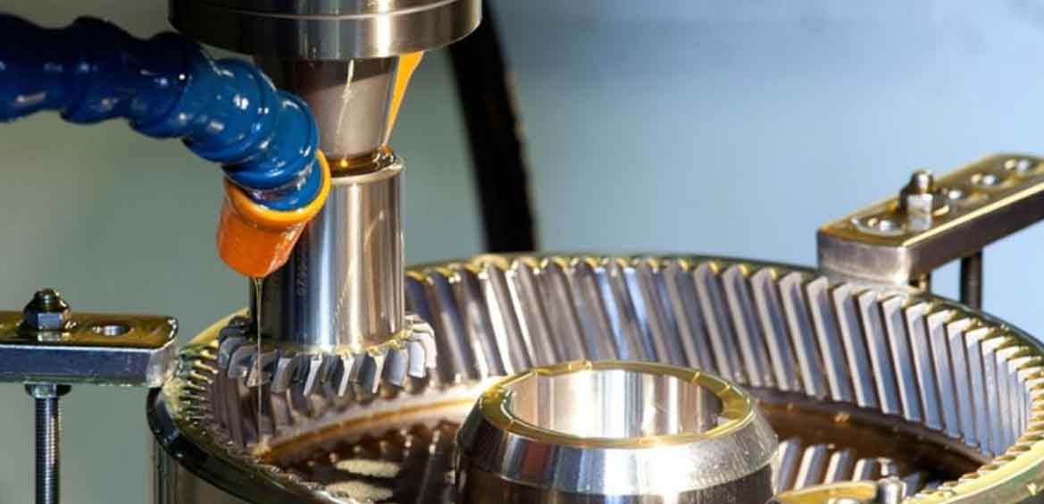
The gear shaping simulation begins with constructing the machine components in SolidWorks and importing them into VERICUT as STL files. The cutter and blank are positioned according to the design parameters, and a CNC program is written in G-code to control the axes. The program includes commands for tool changes, axis movements, and cycle calls to perform the gear shaping operation. For instance, the cutter approaches the blank at a specified offset, engages in a cutting stroke along Z with superimposed rotation on C to form the helix, retracts for clearance, and indexes via coordinated C and A motions to machine subsequent teeth. This cycle repeats until all teeth are generated. The simulation accounts for real-world factors like tool geometry and machine kinematics, providing a realistic depiction of the gear shaping process.
We develop the CNC program based on the motion relationships. A snippet of the code illustrates the gear shaping sequence:
% O0001
T6 M6
CGTECH_MACRO "BroachModeOn" "" 1
G00 X-500 A0
G00 B20
G00 Y-50
G00 Z730
G00 X-390
G00 Z718.8881169 C-79.92758501
G01 Z538.8881169 C-100.132414985
G00 X-500
G00 Z718.8881169
G00 X-390
M98 P0003 L4200
G00 X-600
G00 Z700 C33
G04
This program ensures precise control over the gear shaping motions, enabling the virtual production of a helical offset non-orthogonal face gear. After simulation, the resulting gear model is exported in STL format for analysis. To evaluate the accuracy of the gear shaping process, we compare the simulated tooth surface with the theoretical one from MATLAB. A measurement grid is defined on the active tooth flank, avoiding regions near the tip, root, and edges to focus on the functional area. As shown in Table 2, the grid consists of 7 points along the tooth height and 11 points along the tooth width, totaling 77 measurement locations. The grid boundaries are contracted by 5% of the tooth height and 10% of the tooth width to exclude transition zones.
| Grid Dimension | Number of Points | Contraction | Purpose |
|---|---|---|---|
| Tooth height | 7 | 5% | Exclude tip and root |
| Tooth width | 11 | 10% | Exclude edges |
| Total points | 77 | – | Uniform coverage |
For each grid point \( (i,j) \), we compute the theoretical coordinates \( \mathbf{R}_M(i,j) \) and unit normal \( \mathbf{N}_M(i,j) \) from the MATLAB model. From the VERICUT STL model, we extract the corresponding point coordinates \( \mathbf{R}_V(i,j) \). The normal deviation \( e(i,j) \) is calculated as:
$$ e(i,j) = [\mathbf{R}_M(i,j) – \mathbf{R}_V(i,j)] \cdot \mathbf{N}_M(i,j). $$
This deviation represents the residual error between the simulated and ideal surfaces, with positive values indicating material excess (undercut) and negative values indicating shortage (overcut). The results for both left and right flanks are summarized in Table 3, showing that all deviations are positive, meaning the gear shaping process leaves slight material residue without overcutting. The residuals range from 3.3 to 7.4 micrometers, which aligns with precision standards for gears, such as ISO grade 5 for bevel gears. These minor errors can be attributed to discretization in the simulation, numerical tolerances in VERICUT, and inherent approximations in the gear shaping envelope. The consistency of the residuals validates the effectiveness of the gear shaping approach for manufacturing helical offset non-orthogonal face gears.
| Tooth Flank | Maximum Residual (μm) | Minimum Residual (μm) | Average Residual (μm) |
|---|---|---|---|
| Left | 7.4 | 3.3 | 5.2 |
| Right | 7.2 | 3.9 | 5.5 |
The gear shaping simulation not only confirms manufacturability but also highlights the importance of virtual prototyping in gear design. By iterating parameters in the model, we can optimize the tooth geometry for specific applications, such as minimizing deviations or enhancing load distribution. Furthermore, the integration of gear shaping simulations with finite element analysis could enable predictions of mechanical performance under operational loads. This holistic approach reduces the need for physical prototypes, saving time and costs in development cycles.
In conclusion, this study demonstrates a comprehensive methodology for modeling and simulating helical offset non-orthogonal face gears using gear shaping techniques. We derived the tooth surface equations based on gear meshing principles, implemented numerical modeling in MATLAB, and executed a detailed gear shaping simulation in VERICUT. The virtual manufacturing process successfully generated a gear model with acceptable geometric accuracy, as evidenced by tooth surface deviation analysis. The residuals from the gear shaping simulation were within micrometric ranges, indicating that the process is feasible for producing high-precision gears. These findings pave the way for broader adoption of helical offset non-orthogonal face gears in complex transmission systems, offering designers greater flexibility in spatial layout and performance optimization. Future work could explore adaptive gear shaping strategies, real-time monitoring of machining errors, and experimental validation to further refine the process. Ultimately, the synergy between advanced modeling and gear shaping simulations will continue to drive innovation in gear technology, enabling more efficient and compact mechanical drives across industries.