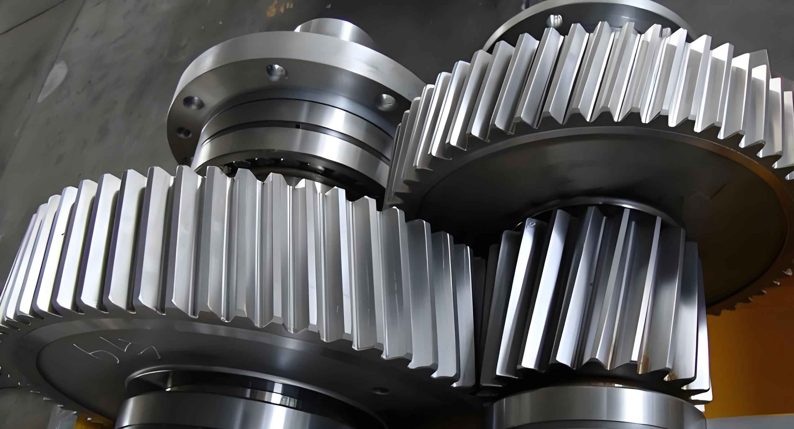
This study investigates the transient meshing behavior and contact stress distribution of helical gears through finite element analysis (FEA). Helical gears are widely recognized for their superior load-bearing capacity, smooth operation, and high transmission efficiency compared to spur gears. However, excessive contact stress and fatigue failure remain critical challenges in gear design. Our analysis combines 3D modeling with advanced transient dynamics simulation to identify stress concentration areas and deformation patterns during gear engagement.
1. Methodology
1.1 Geometric Modeling and Parameters
The helical gear pair was designed using the following fundamental parameters:
| Parameter | Symbol | Value |
|---|---|---|
| Number of teeth | z | 20 |
| Normal module | mn | 2 mm |
| Pressure angle | α | 20° |
| Helix angle | β | 15° |
| Addendum coefficient | ha* | 1 |
| Dedendum coefficient | c* | 0.25 |
The geometric dimensions were calculated using fundamental helical gear equations:
$$ h_a = h_a^* m_n $$
$$ h_f = (h_a^* + c^*) m_n $$
$$ d = \frac{z m_n}{\cos \beta} $$
where \( h_a \), \( h_f \), and \( d \) represent addendum, dedendum, and pitch diameter respectively.

1.2 Material Properties and Meshing
The carbon steel material properties were defined as:
$$ \rho = 7850\ \text{kg/m}^3,\quad E = 200\ \text{GPa},\quad \nu = 0.3 $$
A multi-zone meshing strategy generated 286,354 tetrahedral elements with localized refinement in potential contact regions. The mesh convergence was verified through sensitivity analysis:
| Mesh Level | Element Size (mm) | Max Stress (MPa) | Error (%) |
|---|---|---|---|
| Coarse | 1.2 | 54.3 | 10.2 |
| Medium | 0.8 | 49.8 | 1.1 |
| Fine | 0.5 | 49.3 | – |
1.3 Contact Dynamics Formulation
The transient contact problem was solved using penalty method with friction coefficient \( \mu = 0.15 \). The governing equation for gear dynamics:
$$ [M]\{\ddot{u}\} + [C]\{\dot{u}\} + [K]\{u\} = \{F(t)\} $$
where \( [M] \), \( [C] \), and \( [K] \) represent mass, damping, and stiffness matrices respectively. Boundary conditions included:
- 3° rotational displacement on driving gear
- 1000 N·mm constant torque on driven gear
2. Results and Discussion
The transient simulation revealed critical insights into helical gear meshing behavior:
$$ \sigma_{max} = 49.27\ \text{MPa},\quad \delta_{max} = 0.61\ \text{mm} $$
Stress progression during meshing followed periodic patterns governed by:
$$ \sigma(t) = \sigma_{mean} + \sigma_{amp} \sin(\omega t + \phi) $$
where \( \omega \) represents angular velocity and \( \phi \) phase shift.
3. Conclusion
This investigation demonstrates that maximum contact stress in helical gears occurs at the tooth root region during transient meshing. The developed FEA methodology provides accurate prediction of stress distribution and deformation patterns, enabling optimized gear design against fatigue failure. Future work will incorporate thermo-mechanical coupling effects for enhanced simulation fidelity.
