
The relentless advancement of robotics demands increasingly high-performance components, with the reduction gearbox being a critical element. This drives continuous innovation, aiming both to enhance existing designs and to pioneer new transmission solutions. The RV (Rotate Vector) cycloidal drive has emerged as a prominent solution for robotic joints. Evolving from traditional cycloidal pin-wheel planetary drives, it overcomes many of their limitations while offering a compelling set of advantages: compact size, lightweight construction, a wide range of transmission ratios, exceptional longevity, stable precision retention, high efficiency, and smooth, low-vibration operation. Consequently, the cycloidal drive has garnered significant global attention within the robotics and precision automation industries. This article explores the comprehensive process of creating a three-dimensional digital model for a robotic cycloidal drive, using a typical model, the RV-100, as a case study. We will delve into the modeling of its key components, their assembly into a functional system, and the verification of their kinematic relationships. A particular focus is placed on the mathematical foundation and practical software methods for generating the precise tooth profile of the cycloidal disc, which is the heart of the cycloidal drive.
Structural Principles of the Robotic Cycloidal Drive
The robotic cycloidal drive, specifically the RV-type, is a sophisticated two-stage speed reducer that forms a closed differential gear train. Its operation ingeniously combines two distinct planetary mechanisms in a coaxial layout.
The first stage is a conventional involute helical gear planetary system. A sun gear (input) drives multiple planetary gears (typically three, arranged 120° apart), which rotate within a stationary ring gear. This stage provides an initial speed reduction.
The second, and defining, stage is the cycloidal drive mechanism. The planet gears from the first stage are rigidly connected to crankshafts (eccentric shafts). Two cycloidal discs, offset by 180°, are mounted on these crankshafts via cylindrical roller bearings. These discs mesh with a ring of stationary pin gears (the “pin wheel”). As the crankshafts orbit, they impart a compound motion to the cycloidal discs: an orbital revolution around the central axis and a slower, opposite-direction rotation about their own center. An output mechanism, typically a flange with bearings supporting the crankshafts, captures only the counter-rotation of the cycloidal discs, transmitting it to the output shaft at a 1:1 ratio relative to the disc’s self-rotation. The final, very high reduction ratio is the product of the first-stage gear reduction and the second-stage cycloidal reduction.
Design Parameters and Component Specifications
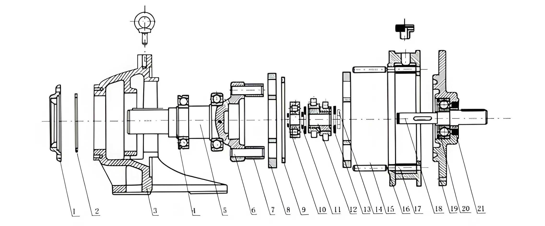
For the purpose of detailed modeling, we define the primary geometrical and operational parameters for our RV-100 case study. The key components requiring modeling include the input gear, the two-stage center gear (a compound gear), the planetary gears, the crankshafts, the cycloidal discs, the pin wheel (housing and pins), and the output flange. The following table summarizes the critical design data.
| Parameter Category | Symbol | Value (RV-100 Example) |
|---|---|---|
| First Stage (Involute Gears) | ||
| Input Gear Teeth | $Z_1$ | 35 |
| Center Gear (Large) Teeth | $Z_2$ | 112 |
| Center Gear (Small) Teeth | $Z_3$ | 48 |
| Planetary Gear Teeth | $Z_4$ | 33 |
| Pressure Angle | $\alpha$ | 20° |
| Planetary Gear Width | $B_4$ | 7 mm |
| Second Stage (Cycloidal Drive) | ||
| Cycloidal Disc Teeth | $Z_c$ | 51 |
| Pin Gear Teeth (Number of Pins) | $Z_p$ | 52 |
| Pin Center Circle Radius | $r_p$ | 102 mm |
| Pin Radius | $r_{rp}$ | 3 mm |
| Eccentricity (Crankshaft Offset) | $e$ | 1.5 mm |
| Cycloidal Disc Width | $B_c$ | 11.5 mm |
Mathematical Foundation: The Cycloidal Tooth Profile
The core challenge in modeling a cycloidal drive lies in accurately defining the tooth profile of the cycloidal disc. This profile is not a simple arc but a complex curve derived from the trochoidal family. The standard tooth form for a pin-engaging cycloidal disc, considering pin radius, is given by a set of parametric equations. These equations describe the path traced by the center of a generating circle (of radius $r_p$) rolling without slipping inside a fixed base circle (of radius $r_p + e \cdot Z_p$), with the profile being the equidistant curve (offset by the pin radius $r_{rp}$) of the generated trochoid.
The coordinates $(x, y)$ of a point on the tooth flank, relative to the disc’s center, are given as functions of a rolling angle parameter $t$:
$$ x(t) = r_p \sin\left(\frac{t}{Z_c}\right) – e \sin\left(\frac{Z_p}{Z_c} t\right) + r_{rp} \left( \frac{\frac{Z_p e}{r_p} \sin\left(\frac{Z_p}{Z_c} t\right) – \sin\left(\frac{t}{Z_c}\right)}{K(t)} \right) $$
$$ y(t) = r_p \cos\left(\frac{t}{Z_c}\right) – e \cos\left(\frac{Z_p}{Z_c} t\right) + r_{rp} \left( \frac{\frac{Z_p e}{r_p} \cos\left(\frac{Z_p}{Z_c} t\right) – \cos\left(\frac{t}{Z_c}\right)}{K(t)} \right) $$
where the auxiliary function $K(t)$ is defined as:
$$ K(t) = \sqrt{1 + \left(\frac{Z_p e}{r_p}\right)^2 – 2 \frac{Z_p e}{r_p} \cos(t) } $$
In these equations, $t$ is the rolling angle in radians, typically evaluated over a range corresponding to one tooth pitch, e.g., $0 \leq t < 2\pi$. The terms involving $r_{rp}$ apply the equidistant offset to account for the finite pin radius, which is crucial for ensuring proper conjugate action and backlash control in the cycloidal drive.
Three-Dimensional Modeling of Key Components
Using SolidWorks, the modeling process for the cycloidal drive components can be systematically executed. The most straightforward components are modeled using standard features, while specialized approaches are needed for gears and the cycloidal disc.
| Component | Modeling Strategy | Key Features & Notes |
|---|---|---|
| Involute Gears (Input, Center, Planet) | Utilize third-party plug-ins like GearTrax or Toolbox. | Input module, pressure angle ($\alpha$), tooth counts ($Z_1, Z_2/Z_3, Z_4$), face width. Ensures accurate involute geometry for proper meshing simulation. |
| Crankshaft | Revolve and Extrude features. | Creates the main journal, eccentric lobes (phase offset by 180° for the two discs), and splined/keyed ends for connection to planetary gears. |
| Pin Wheel (Housing & Pins) | Housing: Revolve. Pins: Extrude + Circular Pattern. | Pin circle radius ($r_p$) is critical. Pins are modeled as cylinders with radius $r_{rp}$ and patterned with count $Z_p$. |
| Output Flange / Input Flange | Extrude, Revolve, and Hole Wizard. | Includes bearing seat bores, bolt hole patterns, and interface features for connecting to the robot arm and motor. |
| Bearings (Deep Groove, Tapered, Needle) | Simplified representations or manufacturer CAD models. | Inner/outer rings and rolling elements (balls, rollers) are modeled. For tapered and needle bearings, careful attention to contact angles is needed for assembly constraints. |
Cycloidal Disc Modeling: Two Practical Methods in SolidWorks
Since SolidWorks does not have a native “cycloidal curve” command, the tooth profile must be generated indirectly. Two robust methods are presented below for creating the essential tooth profile sketch, which can then be extruded to form the disc body. Additional features like the central bore and crank pin holes are added afterward.
Method 1: Curve Through XYZ Points (External Data Import)
This method leverages external computational power for high-precision point generation.
- Data Generation: Write a program in a language like C++, Python, or MATLAB to evaluate the parametric equations $$x(t)$$ and $$y(t)$$. The program iterates over the parameter $t$ with a sufficiently small step size (e.g., $\Delta t = 0.01$ rad) to generate a dense set of $(x, y)$ coordinate pairs for one complete tooth profile.
- Data Formatting: Save the coordinate list in a plain text file (.txt), with each line containing the X, Y, and Z (set to 0) coordinates separated by tabs or commas.
- SolidWorks Import: In a new part file, navigate to Insert > Curve > Curve Through XYZ Points…. Browse and select the generated text file. SolidWorks will create a fitted curve through all the imported points.
- Profile Completion: Use this imported curve to create a closed sketch profile for a single tooth valley. This profile is then extruded to the disc width $B_c$. The final disc is created by circularly patterning this tooth feature $Z_c$ times around the central axis.
This method is highly accurate and allows for easy modification of the underlying equations, making it ideal for research and development of customized cycloidal drive profiles.
Method 2: Equation Driven Curve (Native SolidWorks Feature)
This method works entirely within the SolidWorks sketching environment, offering greater immediacy.
- Sketch Entry: In a new part file, create a new sketch on the Front Plane.
- Insert Equation: Go to Tools > Sketch Entities > Equation Driven Curve….
- Define Parameters: Select the “Parametric” option. In the input fields, directly enter the parametric equations derived earlier. For the X(t) equation, you would input the full expression for $$x(t)$$, using `t` as the variable. For Y(t), input the expression for $$y(t)$$.
- Set Parameter Range: Define the range for $t$, for example, from $0$ to $2\pi$ (or a segment thereof defining one tooth).
- Generate and Complete: Click OK. SolidWorks will generate the curve segment within the sketch. As with Method 1, this curve is used to define a tooth profile, which is then extruded and patterned.
While convenient, this method requires careful syntax and can be less stable with very complex equations. It represents the most integrated workflow within the SolidWorks environment for generating a cycloidal drive disc profile.
Virtual Assembly of the Cycloidal Drive
The assembly of the complex cycloidal drive is best approached using a bottom-up strategy, combined with a hierarchical sub-assembly structure to manage complexity.
1. Creating Sub-Assemblies
Breaking down the assembly into logical groups simplifies mate definition and improves rebuild performance.
| Sub-Assembly | Components | Key Mating Strategy |
|---|---|---|
| Crankshaft Assembly | Crankshaft, 2x Needle Roller Bearings, 2x Tapered Roller Bearings, Spacers. | Needle bearings are mated to the eccentric lobes using tangent mates (rollers to shaft) and coincident mates (side faces). Tapered bearings are concentrically and axially aligned at each end of the shaft. |
| Pin Wheel Assembly | Pin Wheel Housing, Pin Gears (needles). | Each pin is mated concentrically and coincidently to its hole in the housing. The entire set is created using a circular pattern feature based on pin count $Z_p$. |
| Bearing Sets | Deep Groove Ball Bearings, Angular Contact Ball Bearings. | Pre-assembled as standalone components or simplified representations for placement in the main assembly. |
2. Main Assembly Sequence and Mating Logic
The final assembly brings all parts and sub-assemblies together. The mating sequence follows the physical construction logic of the cycloidal drive.
- Base Component: Fix the Output Flange in space.
- Pin Wheel & Bearings: Insert the Pin Wheel Assembly. Mate it concentrically and with a coincident face to the Output Flange. Insert an Angular Contact Bearing into the opposite side of the Pin Wheel housing.
- Crankshaft Assemblies: Insert the three Crankshaft Assemblies. Mate the outer races of their Tapered Roller Bearings concentrically and axially into the corresponding holes in the Output Flange.
- Cycloidal Discs: Insert the two cycloidal discs (180° offset). Mate their central bores concentrically with the Pin Wheel housing. Apply tangent mates between the cylindrical surfaces of the Needle Roller Bearings (on the crankshaft eccentrics) and the inner raceways of the holes in the cycloidal discs. This critical mate simulates the rolling contact.
- Input Stage & Flange: Insert the Input Flange. Mate it to the previously placed Angular Contact Bearing and to the splined ends of the three crankshafts (using concentric and coincident mates for spline simulation). Secure it to the Output Flange with bolt mates.
- Planetary Gears: Insert the three Planetary Gears. Mate them concentrically to the crankshaft ends (spline/key simulation) and ensure proper axial positioning.
- Center (Sun) Gear: Insert the compound Center Gear assembly. Support it with a Deep Groove Ball Bearing mated to the Input Flange. Apply gear mates (mechanical mates in SolidWorks) between the small sun gear ($Z_3$) and the three Planetary Gears ($Z_4$), defining the correct gear ratio. The large sun gear ($Z_2$) remains unmeshed in this model as its ring gear counterpart is typically the housing.
- Input Gear: Finally, insert the Input Gear and mate it to the motor interface on the Input Flange.
3. Design Validation and Presentation
Once assembled, the model serves as a powerful tool for validation and communication.
Interference Detection: SolidWorks’ Interference Check tool is run to ensure no unintended volumetric overlaps exist between components, verifying the correctness of clearances and fits in the cycloidal drive design.
Collision Detection & Motion Study: A basic Motion Study can be created by applying a rotary motor to the input gear. Using collision detection and physical dynamics, one can visually verify that the compound motion of the planetary gears, crankshafts, and cycloidal discs leads to the slow, steady rotation of the output flange, confirming the kinematic chain.
Exploded View Creation: For manufacturing and service documentation, an exploded view is essential. The view is created by dragging components along appropriate axes (typically radial and axial directions). The sequence should logically reflect the disassembly/assembly order.
Animation: Using the SolidWorks Animation wizard, the explosion sequence can be turned into an AVI or MP4 video. This is an invaluable tool for illustrating the spatial relationships and assembly procedure of the complex cycloidal drive to teams in manufacturing, maintenance, and sales.
Conclusion
The digital modeling and assembly of a robotic cycloidal drive is a multi-faceted engineering task that bridges theoretical kinematics, precision geometry, and modern CAD practice. This detailed walkthrough, centered on an RV-100 type reducer, has outlined the complete workflow. We established the mathematical bedrock with the parametric equations defining the cycloidal tooth profile and demonstrated two pragmatic methods for implementing this geometry in SolidWorks: external point import and native equation-driven curves. The subsequent bottom-up assembly strategy, utilizing sub-assemblies for complex components like the crankshafts, provides a manageable and robust approach to constructing the full system virtually. Tools for interference checking, motion simulation, and explosive view animation transform the static model into a dynamic prototype for design validation, troubleshooting, and communication. This comprehensive digital model forms the indispensable foundation for further advanced analyses, including Finite Element Analysis (FEA) for stress and deformation, computational fluid dynamics (CFD) for lubrication flow, and ultimately, the generation of manufacturing drawings for this high-precision cycloidal drive component.