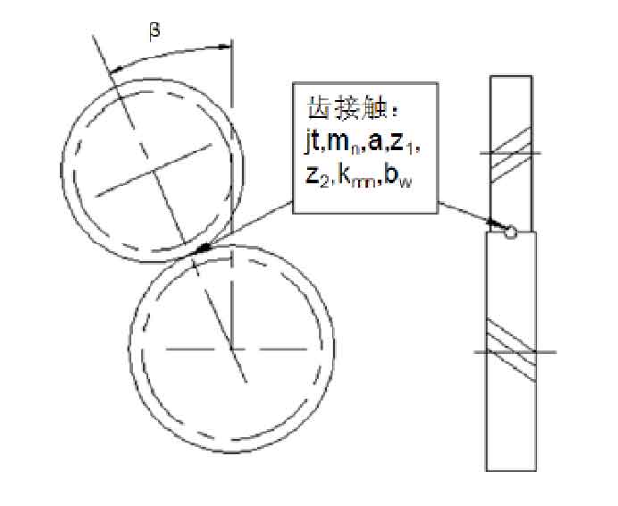
The planetary gear transmission system of hybrid electric vehicle studied is composed of composite planetary gear mechanism and parallel axis mechanism. There is no corresponding physical module in the simulation X model library, but there is a corresponding substructure model in the model library. It constitutes the basic model of all planetary gear structures. This model allows the dynamic simulation of any number of elastically mounted planetary gearboxes, taking into account time-varying meshing stiffness, tooth side clearance and other nonlinear factors, as well as all relevant tooth meshing parameters. Therefore, the basic model base structures oom in the simulationx software planetary structures is used to replace the meshing of each pair of planetary gears of the composite planetary gear mechanism. The significance of the basic parameters is shown in Figure 1.
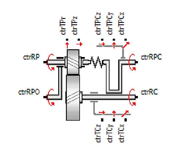
The model symbol is shown in Figure 2, and the meaning and specific functions of each node are shown in the table.
| Node symbol | Functional interpretation | Node symbol | Functional interpretation |
| ctrTCx | Element connected to the radial X direction of the center wheel | ctrTPz | Elements connected to the planetary axle in the Z direction |
| ctrTCy | Elements connected to the radial Y direction of the center wheel | ctrRP | Elements connected to the epicyclic direction of the planetary gear |
| ctrTCz | Elements connected to the radial Z direction of the center wheel | ctrTPCx | Elements connected to planet carrier in radial X direction |
| ctrTRC | Components connected to the turning direction of the center wheel | ctrTPCy | Elements connected to planet carrier in radial Y direction |
| ctrRPo | The planetary gear element rotates in the Z direction around the center wheel | ctrTPCz | Elements connected to the axial Z direction of the planet carrier |
| ctrTPr | Elements connected to the planetary gear radial | ctrRPC | Elements connected to the rotation direction of the planet carrier |
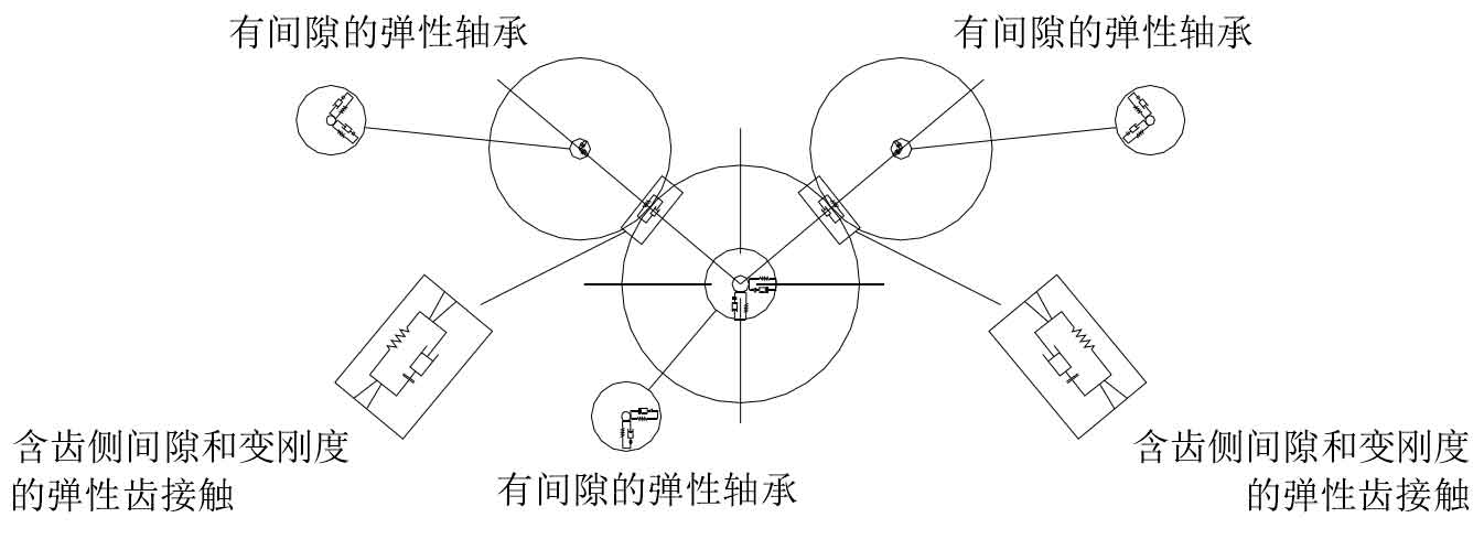
The planetary gear model can consider the time-varying stiffness of tooth meshing and the damping stiffness of elastic bearing along radial and axial directions. Its structural model is shown in Figure 3.
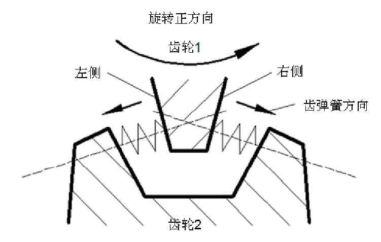
The related concepts of time-varying meshing stiffness have been defined in the previous chapter. In addition, when the teeth contact, a normal force is provided on the left and right sides of the teeth at the same time. The definition of the left and right sides corresponding to different planetary gear teeth is explained in Fig. 4. As the planetary gear rotates, the contact surface of the teeth will also change, and the corresponding meshing stiffness and the position and direction of the normal force will also change.
In addition, the calculation of planetary gear meshing force is the product of the deformation and stiffness of the tooth surfaces on both sides between the teeth. Therefore, the tooth side deformation and the corresponding speed difference during operation can also be obtained in the analysis process.


