
In the realm of mechanical transmission systems, the spiral bevel gear stands out due to its exceptional attributes, including high overlap ratio, efficient power transmission, substantial load-bearing capacity, smooth operation, and reduced noise levels. These qualities make the spiral bevel gear indispensable in critical industries such as aerospace and automotive engineering. However, the complex tooth geometry of the spiral bevel gear, coupled with escalating demands for precision in manufacturing, presents significant design challenges. Traditional design methodologies often operate in isolation, leading to inefficiencies and limitations in achieving high accuracy and flexibility. To address these issues, we explore the integration of networked collaborative design principles, specifically through Web Services, to develop a comprehensive collaborative design system for spiral bevel gear tooth surfaces. This system aims to streamline the entire lifecycle of gear design, from simulation and modeling to optimization and validation, thereby enhancing productivity, precision, and adaptability in the design process for spiral bevel gears.
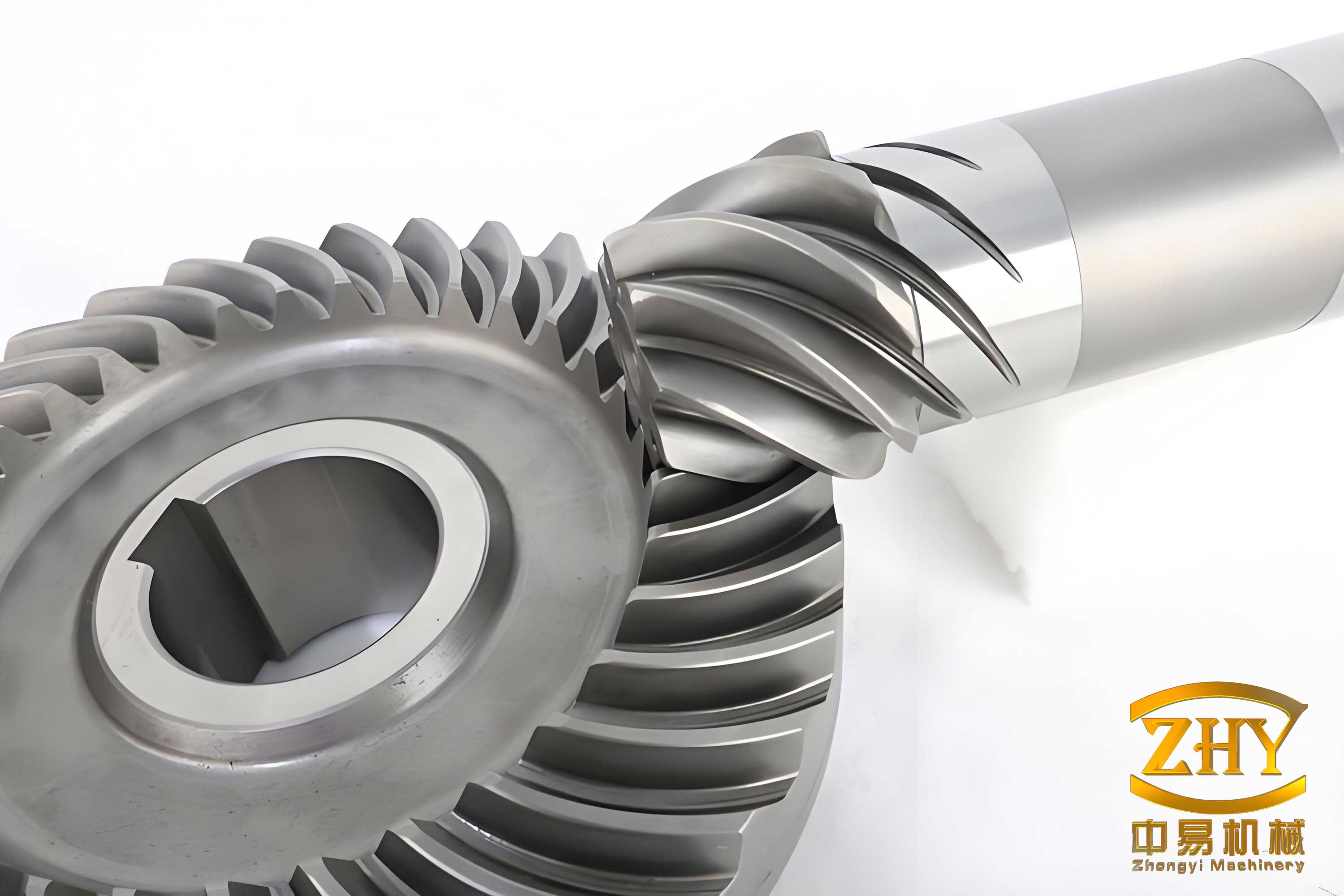
The design of spiral bevel gears has long been a focal point for researchers, driven by the need for advanced modeling techniques. Early work in this field relied on spatial meshing principles to derive tooth surface equations, often using specialized software for data processing and visualization. For instance, studies have employed simulation-based approaches to emulate gear generation processes, where the envelope of cutting tool paths forms the tooth surface, providing a foundation for virtual machining. Subsequent refinements have enhanced the accuracy of these simulations, enabling more precise tooth surface design. Despite these advances, the increasing globalization and demand for customized solutions necessitate a shift toward collaborative frameworks that integrate diverse design, manufacturing, and inspection tasks. A holistic system for spiral bevel gear design must encompass: (1) simulation based on actual machining parameters to generate basic models, (2) advanced modeling techniques for tooth surface refinement to improve accuracy, and (3) performance validation using specialized software. By leveraging Web Services and collaborative design paradigms, we propose a system that unifies these elements, fostering efficient resource sharing and interactive coordination among distributed teams working on spiral bevel gear projects.
To realize this vision, we have developed key technologies and support systems tailored for the collaborative design of spiral bevel gears. These components form the backbone of our integrated platform, ensuring seamless interaction and high-performance outcomes for spiral bevel gear applications.
Key Technologies for Collaborative Design of Spiral Bevel Gears
The design of spiral bevel gear tooth surfaces primarily relies on simulation machining, which involves multiple software platforms such as MATLAB for equation solving, Pro/ENGINEER for model generation, and UG for NC code simulation. To facilitate interoperability among these heterogeneous systems, we adopt a collaborative simulation technology based on the High-Level Architecture (HLA). HLA serves as a soft bus that standardizes interfaces, allowing commercial simulation tools to function as federates within a unified framework. This approach enables real-time data exchange and synchronization, critical for accurate spiral bevel gear modeling. The process for general-purpose machine tool simulation, as applied to spiral bevel gears, can be summarized in the following table:
| Step | Description | Software Platform |
|---|---|---|
| 1. Integrated Modeling | Determine design scheme and extract tooth surface information from reference models. | Pro/ENGINEER, UG |
| 2. Boolean Cutting Simulation | Perform virtual cutting by setting configurations and process parameters to generate NC code. | UG, CATIA, ADAMS |
| 3. Collaborative Simulation via HLA | Integrate platforms through HLA adapters for synchronized execution and management. | MATLAB, Pro/E, UG, etc. |
| 4. Result Validation | Verify design outcomes against specifications using simulation data. | Custom validation tools |
This workflow ensures that the simulation of spiral bevel gear machining is cohesive and efficient, reducing errors and enhancing design reliability. For example, the HLA framework manages the interaction between a MATLAB federate computing tooth surface points and a UG federate simulating the cutting process, allowing for iterative refinement of the spiral bevel gear model.
Beyond simulation, optimizing the tooth surface of a spiral bevel gear is crucial for achieving high precision. We employ Non-Uniform Rational B-Splines (NURBS) for this purpose, given their superiority in CAD/CAM applications, including excellent curve-fitting capabilities and local control. NURBS is the standard mathematical method in STEP for product shape definition, making it ideal for representing complex spiral bevel gear geometries. The optimization process involves error analysis of the simulated tooth surface, extraction of optimal data points, and NURBS-based reconstruction. This can be expressed mathematically through NURBS surface formulation:
$$S(u,v) = \frac{\sum_{i=0}^{n} \sum_{j=0}^{m} N_{i,p}(u) N_{j,q}(v) w_{i,j} P_{i,j}}{\sum_{i=0}^{n} \sum_{j=0}^{m} N_{i,p}(u) N_{j,q}(v) w_{i,j}}$$
where $N_{i,p}(u)$ and $N_{j,q}(v)$ are B-spline basis functions, $P_{i,j}$ are control points, and $w_{i,j}$ are weights. For spiral bevel gears, we apply three refinement techniques: (1) Energy-based global interpolation of surface points to ensure smoothness by minimizing strain energy, (2) Least-squares surface approximation to optimize control point distribution, and (3) Newton iteration for parameterization of data points to enhance accuracy. The optimization steps are outlined below:
- Error Analysis: Compute deviations such as tooth length error, height error, and diagonal error from the simulated spiral bevel gear surface.
- Point Extraction: Identify optimal data points that define the tooth surface geometry of the spiral bevel gear.
- NURBS Fitting: Use boundary curve fitting and skinning methods to reconstruct the surface.
- Refinement: Apply energy minimization, least-squares, and Newton iteration to fine-tune the spiral bevel gear surface.
This methodology not only improves the accuracy of spiral bevel gear designs but also ensures manufacturability by producing smooth, continuous surfaces. For instance, the energy minimization problem can be formulated as:
$$\min \sum E(S) \text{ subject to } S(u_i, v_j) = Q_{i,j}$$
where $E(S)$ represents the strain energy of the NURBS surface $S$, and $Q_{i,j}$ are the target data points from the spiral bevel gear simulation.
Support Systems for Collaborative Design of Spiral Bevel Gears
To manage the complexity of collaborative workflows in spiral bevel gear design, we have implemented several support systems that enhance coordination and control. These systems are integral to maintaining efficiency and quality throughout the design lifecycle of spiral bevel gears.
Task-Based Design Process Integration System: This system decomposes the overall design of a spiral bevel gear into manageable subtasks, each with defined objectives, timelines, and constraints. The workflow, as shown in the table below, facilitates task creation, assignment, execution, and monitoring:
| Phase | Activity | Outcome |
|---|---|---|
| Task Creation | Define main task and subtasks for spiral bevel gear design (e.g., simulation, optimization). | Task tree and schedule |
| Task Assignment | Assign subtasks to team members based on expertise. | Distributed workload |
| Task Execution | Perform design activities using CAD tools, with progress tracking. | CAD models, documents |
| Task Submission | Submit results for review and approval. | Validated outputs |
| Constraint Management | Enforce design rules and standards for spiral bevel gears. | Compliance assurance |
| Task Monitoring | Monitor changes and updates in real-time. | Adaptive adjustments |
This approach ensures that collaborative efforts in spiral bevel gear projects are structured and transparent, reducing delays and errors. For example, a task for optimizing a spiral bevel gear tooth surface might involve multiple iterations, with the system tracking each change and ensuring consistency.
Constraint-Grid-Based Design Monitoring System: During the design of spiral bevel gears, modifications to parameters or methods are common and can impact overall efficiency. Our monitoring system uses a constraint grid to oversee all design activities, enabling orderly and timely updates. It consists of two modules: permission settings and history management. The constraint grid assigns roles and privileges, allowing controlled access to design data for spiral bevel gears. Changes are logged and analyzed for consistency, with the grid updated accordingly. This can be modeled as a constraint satisfaction problem:
$$C(x_1, x_2, \dots, x_n) \leq \epsilon$$
where $C$ represents constraints (e.g., geometric tolerances for a spiral bevel gear), $x_i$ are design variables, and $\epsilon$ is a permissible error threshold. The system relaxes constraints iteratively to grant permissions, ensuring that modifications to the spiral bevel gear design do not compromise integrity.
Web Services-Based Parts Library System: After designing a spiral bevel gear, storing its model and data for reuse is essential. Our parts library system, built on Web Services, allows users to catalog and retrieve gear components via standardized interfaces. Each spiral bevel gear model is assigned a unique ID and stored with associated documentation (e.g., tooth surface data, performance specs). This enables downstream applications such as Tooth Contact Analysis (TCA) or sales promotions, saving costs and boosting competitiveness for spiral bevel gear products. The library supports queries like:
$$\text{Query}( \text{gear_type} = \text{“spiral bevel gear”}, \text{module} = m, \text{pressure angle} = \alpha )$$
which returns relevant models for collaborative design sessions. This system fosters knowledge sharing and accelerates the development of new spiral bevel gear variants.
Integrated Platform Framework for Spiral Bevel Gear Collaborative Design
Building upon these technologies and systems, we have constructed an integrated platform framework for collaborative design of spiral bevel gear tooth surfaces. This framework, grounded in Web Services, supports distributed design and manufacturing environments, making it suitable for small and medium enterprises involved in spiral bevel gear production. It also aligns with emerging trends like cloud manufacturing for spiral bevel gears. The framework is organized into three layers: the collaborative interaction system, the collaborative design application system, and the collaborative design integration platform, as detailed in the table below:
| Layer | Components | Functionality for Spiral Bevel Gears |
|---|---|---|
| Collaborative Interaction System | User interface, client-side applications | Facilitates communication between customers and designers for requirements gathering on spiral bevel gears. |
| Collaborative Design Application System | Key technologies (HLA simulation, NURBS optimization) and support systems (task management, monitoring) | Executes core design tasks, such as simulating spiral bevel gear machining and optimizing tooth surfaces. |
| Collaborative Design Integration Platform | Application services, data layer, protocol layer (HTTP, STEP, XML) | Provides services like document management, model browsing, and data integration for spiral bevel gear projects. |
The platform leverages standard protocols such as STEP and XML for product data exchange, ensuring interoperability. For example, spiral bevel gear models are described using STEP AP214, allowing seamless import/export across CAD systems. The application services layer offers functionalities like design resource management and virtual assembly, which are critical for evaluating spiral bevel gear performance in virtual environments. Mathematical models underpinning these services include optimization algorithms for spiral bevel gear design, such as:
$$\text{Minimize } f(x) = \sum (y_i – \hat{y}_i)^2 \text{ for gear parameters } x$$
where $f(x)$ represents an objective function (e.g., minimizing transmission error in a spiral bevel gear), $y_i$ are simulated outcomes, and $\hat{y}_i$ are target values. This integrated approach enables a complete design cycle for spiral bevel gears, from requirement confirmation and scheme negotiation to execution, optimization, validation, and final product completion. By harnessing networked collaboration, the platform addresses the need for high efficiency, precision, and flexibility in spiral bevel gear design, which is increasingly vital in globalized markets.
Conclusions and Future Directions
In this research, we have explored the modeling of a collaborative design system for spiral bevel gears, combining advanced design theories with networked technologies. By emphasizing simulation-based modeling and introducing key technologies like HLA-based collaborative simulation and NURBS-based optimization, we have developed a framework that enhances the speed and accuracy of spiral bevel gear tooth surface design. The support systems, including task management and constraint monitoring, further streamline collaborative processes, ensuring that design modifications are managed effectively. Our integrated platform unifies distributed and heterogeneous resources, enabling seamless information sharing and interactive coordination for spiral bevel gear projects. This contributes to the digital transformation of spiral bevel gear design and manufacturing, offering a reference for future developments in networked collaborative systems.
Looking ahead, the trend toward globalization will likely drive greater adoption of networked design and manufacturing for spiral bevel gears. Our system lays a foundation for extending into areas like cloud-based design services or AI-driven optimization for spiral bevel gears. Potential enhancements include integrating real-time data from IoT sensors in manufacturing environments to refine spiral bevel gear simulations, or applying machine learning algorithms to predict performance outcomes based on historical spiral bevel gear data. Continued research in these directions will further elevate the capabilities of collaborative systems, ensuring that spiral bevel gear design remains at the forefront of technological innovation. Ultimately, the synergy between collaborative design methodologies and spiral bevel gear engineering promises to deliver more robust, efficient, and customizable solutions for industrial applications worldwide.
To summarize, our work demonstrates that a Web Services-based collaborative design system can significantly improve the lifecycle management of spiral bevel gears. By fostering collaboration among diverse stakeholders and leveraging computational tools, we can achieve higher precision and flexibility in gear design. This is exemplified through our detailed exploration of simulation techniques, optimization methods, and support systems, all tailored to the unique challenges of spiral bevel gear engineering. As industries evolve, such collaborative frameworks will become indispensable for maintaining competitiveness and meeting the growing demands for high-performance spiral bevel gears in sectors like aerospace, automotive, and beyond. We encourage further experimentation and adaptation of our model to suit specific industrial contexts, with the goal of advancing the state-of-the-art in spiral bevel gear design and manufacturing.