
1. Crack propagation path
Although there is uncertainty in the location and propagation path of cracks in helical gears, research has found that there are still laws that can be found. Cracks often occur at the stress concentration area where the root of the helical gear is excessively circular. Simulation shows that there may be multiple cracks at the beginning, but eventually they will continue to propagate along the one with the highest crack factor (SIF). As shown in Figure (a), starting from point A on the transition circle, where the tangent at point A has an angle of 30 ° with the centerline of the helical gear teeth.
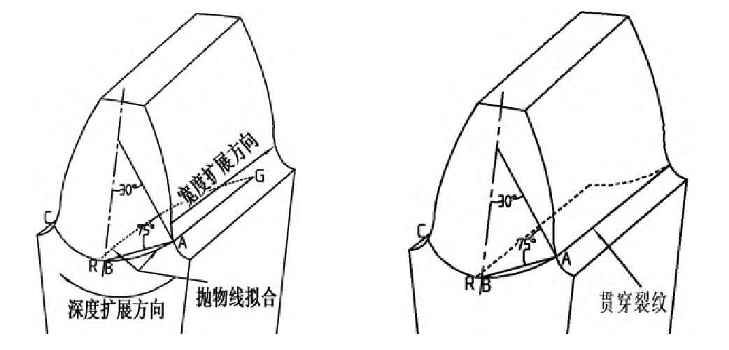
As shown in Figure (a), a parabolic ABC is used for meshing in the depth direction of a non penetrating crack. A is the starting point of the crack, C is the end point of the pseudo crack, A and C are symmetrical about the axis of the helical gear teeth, and B is the line connecting the lowest point AB of the parabolic curve with a centerline angle of 75 °. R is a point on the parabolic ABC, and AR is the actual crack depth. The propagation of cracks at the root of helical gears in the width direction is simulated using parabolic RG, where the vertex of the parabola is R, and G is the point in the width direction of the crack. The parameters of the parabola are determined by AG and AR.
Figure (b) shows a through type crack, with the depth direction fitted in the same way as a parabola, and the width direction running in a straight line throughout the entire width of the helical gear teeth.
2. Definition of the degree of crack propagation at the root of helical gears
In order to quantitatively analyze different cracks, the crack propagation degree is defined as follows
(1) Depth direction crack degree
Defined as the percentage of actual crack depth to maximum crack depth, which is:
Actual crack depth/maximum crack depth=AR/ABC
Four different depths are used, namely 10%, 20%, 50%, and 80%.
(2) Width direction crack degree
| Parameters | Planetary gear | Solar wheel |
| Number of teeth z | 32 | 25 |
| Normal modulus m/mm | 20 | 20 |
| Pressure angle α/ (°) | 20 | 20 |
| Helix angle β/ (°) | 7.5 | 7.5 |
| Tooth width b/mm | 120 | 120 |
From the table, it can be seen that the width of the sun gear teeth is 120mm. In this article, four different types of cracks are selected in the direction of width expansion, with widths of 30mm, 60mm, 90mm, and 120mm, respectively. The corresponding percentages are 25%, 50%, 75%, and 100%. Set the thickness of the crack to 0.02mm.