
In the field of modern mechanical transmission, hypoid gears have attracted extensive attention and application due to their unique geometric characteristics and outstanding transmission performance. The research described in this thesis focuses on the solid modeling of hypoid gears machined by the HFM method, the development of computer programs for tooth contact analysis (TCA), and the investigation of typical pinion control parameters adjustment. The primary goal is to provide reliable machining parameters for the actual production of hypoid gears. In this chapter, I will comprehensively elaborate on the theoretical foundations, mathematical model construction, numerical solution algorithms, and engineering application results. The study is expected to contribute to the digital design and manufacturing technology system for hypoid gears.
The research background of this work is rooted in the practical demands of large-scale hypoid gear processing equipment development. The digitalization, informatization, and intelligent manufacturing trends have greatly promoted the integration of digital technologies into advanced design and manufacturing fields, leading to significant progress in mechanical engineering. However, the high-end gear transmission devices still face common problems such as short service life, poor reliability, and heavy structure. Therefore, it is of great importance to conduct fundamental research on hypoid gears, especially on the key technologies of gear design and manufacturing.
My research work is mainly composed of three parts: establishing the mathematical model of the tooth surface for hypoid gears based on the HFM method and constructing the solid model; establishing the TCA mathematical model and programming the computerized calculation procedure, while focusing on solving the initial value problem of the nonlinear equations; and finally, studying the influence of typical pinion control parameters on TCA results and summarizing the adjustment laws. These components together form a complete technical route for the digital design and machining parameter optimization of hypoid gears.
1. Introduction
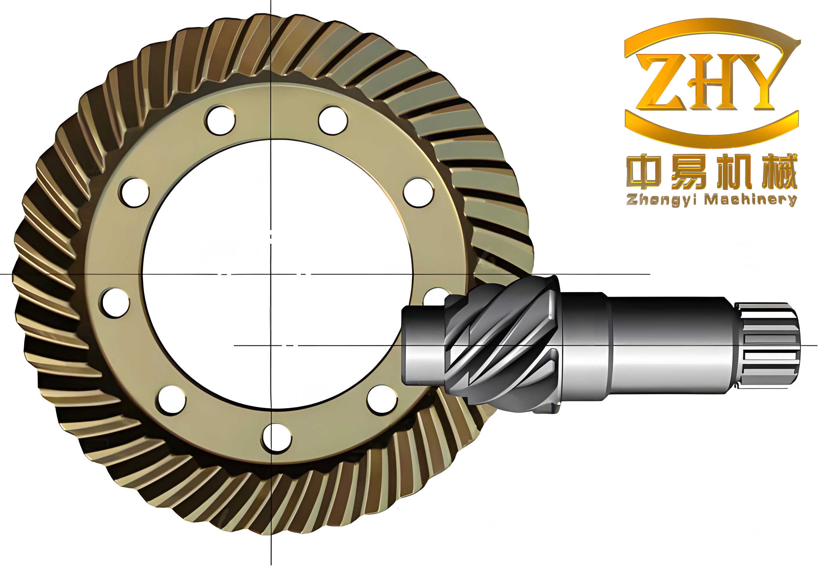
hypoid gears, which are a type of spiral bevel gear with offset axes, possess several well-known advantages, including high load-carrying capacity, large contact ratio, and smooth transmission. These characteristics make hypoid gears widely used in the automotive, mining, aerospace, and other industrial sectors. With the rapid development of modern engineering, the performance requirements for hypoid gear transmission have become increasingly stringent. The low-noise, high-strength, and long-life requirements call for more accurate design and manufacturing techniques.
According to the tooth trace on the pitch cone, spiral bevel gears can be mainly divided into two categories: the circular arc tooth type and the extended epicycloid tooth type. The typical manufacturers include the American Gleason Company and the German Klingelnberg Company. In China, the circular arc tooth system is extensively used, so this thesis focuses on the Gleason circular arc hypoid gears. Because foreign countries strictly block the core technologies, and the domestic industrial foundation used to be relatively weak, Chinese researchers have faced considerable challenges in the independent development of hypoid gear design and machining technologies. Over the years, with great effort, a relatively complete theoretical system for hypoid gear design and processing has been established in China.
One of the great challenges in the field is that the tooth surfaces of a practical hypoid gear pair are not the mathematically conjugate surfaces in the strict sense. The tooth surface geometry depends on the machine tool settings and cutting parameters. Different machine tools and setting parameters will produce gears with completely different tooth surface geometries. Therefore, it is essential to investigate the relationship between machining parameters and tooth surface performances. The gear tooth contact analysis (TCA) technique is exactly an effective tool to evaluate the meshing performance before real machining, providing guidance for parameter selection and optimization.
The main contents of this thesis are as follows. First, according to the meshing principle and gear cutting principle, the mathematical models of hypoid gear tooth surfaces machined by the HFM method are established. The three-dimensional coordinates of discrete tooth surface points are obtained through numerical methods, and the solid model of the hypoid gear pair is constructed using the SolidWorks software platform. Second, the principle of TCA for hypoid gears is studied, the TCA mathematical model is established, and a computerized program is developed. The automatic calculation algorithm for the initial contact point used in HGM method TCA is extended to the HFM method TCA. Third, based on the HFM method TCA, the corrections of typical pinion control parameters that significantly affect the contact pattern diagram and transmission error curve are studied, and the corresponding adjustment rules are summarized.
2. Fundamental Principles of Conjugate Surfaces for Hypoid Gears
The theoretical foundation of gear meshing lies in the conjugate surface principle. In the following, I will discuss the basic equations of conjugate surfaces, the meshing equation, the relative normal curvature, and the concept of equidistant conjugate surfaces, which are crucial for the subsequent derivation of tooth surface models and TCA.
2.1 Meshing Equation
As shown in the coordinate system definitions, two moving coordinate systems are attached to a pair of conjugate surfaces, and the contact point must satisfy both the position vector equation and the unit normal vector equation. Let r₁ and n₁ denote the position vector and unit normal vector of point M on surface S1, respectively, and r₂ and n₂ denote those on surface S2. The fundamental equations for gear transmission are:
$$ \mathbf{r}_2 = \mathbf{m} + \mathbf{r}_1, \quad \mathbf{n}_2 = \mathbf{n}_1 $$
Differentiating the first equation with respect to time and considering the relative velocity v₁₂ at the contact point yields the differential relationship between the two surfaces. The condition for continuous meshing is that the relative velocity is orthogonal to the common normal vector:
$$ \mathbf{v}_{12} \cdot \mathbf{n} = 0 $$
This is called the meshing equation. It states that the normal components of the velocities of the two surfaces at the contact point must be equal so that the two surfaces maintain continuous contact. The relative angular velocity of the two conjugate surfaces is:
$$ \boldsymbol{\omega}_{12} = \boldsymbol{\omega}_1 – \boldsymbol{\omega}_2 $$
and the relative velocity can also be expressed as:
$$ \mathbf{v}_{12} = \boldsymbol{\omega}_{12} \times \mathbf{r}_1 – \boldsymbol{\omega}_2 \times \mathbf{m} + \dot{\mathbf{m}} $$
2.2 Induced Curvature of Conjugate Surfaces
Using the relative differential method, the differential relationship along the conjugate direction is:
$$ d\mathbf{n}_2 = d\mathbf{n}_1 + \boldsymbol{\omega}_{12} \times \mathbf{n} \, dt $$
By differentiating the meshing equation with respect to time and introducing the parameter q, we can derive the relationship between dt and the surface parameters. Let v denote the unit vector along the relative velocity direction. The induced normal curvature along the v direction between the two conjugate surfaces is:
$$ \Delta k_{nv} = k_{nv}^{(1)} – k_{nv}^{(2)} = \frac{(av)^2}{qn + av} $$
Here, the induced geodesic torsion is:
$$ \Delta \tau_{gv} = \tau_{gv}^{(1)} – \tau_{gv}^{(2)} = \frac{av(a,n,v)}{qn+av} $$
where a is a vector related to the relative motion and surface parameters. Further, the induced normal curvature in a general direction α can be expressed by the Euler formula:
$$ \Delta k_{n\alpha} = \frac{(a\alpha)^2}{qn + av} $$
For the direction e along the contact line, the induced curvature is zero. This property is important for the analysis of local contact. The angle ω between the contact line direction and the first principal direction can be computed by:
$$ \tan \omega = -\frac{av}{at} $$
2.3 Equidistant Conjugate Surfaces
Consider a pair of completely conjugate surfaces S1 and S2 contacting at point M. Their equidistant surfaces, denoted as S1h and S2h, also contact at the corresponding point Mh. The position vector of the equidistant surface is:
$$ \mathbf{r}_1^h = \mathbf{r}_1 + h \mathbf{n} $$
If the original surfaces satisfy the meshing equation at M, then the equidistant surfaces also satisfy the meshing equation at Mh. Thus, they are conjugate about the same relative motion. The relationship between the principal curvatures and the induced curvatures of the original and equidistant conjugate surfaces can be established:
$$ \tan \omega^h = \frac{1 – h/\rho_1}{1 – h/\rho_2} \tan \omega $$
$$ \Delta k^h = \frac{1}{(1 – h/\rho_1)(1 – h/\rho_2)} \left[ \Delta k + \frac{h}{ (1 – h/\rho_1)(1 – h/\rho_2) } \left( \frac{\tan^2 \omega}{\rho_1} + \frac{1}{\rho_2} \right) \right] $$
These formulas enable us to transform the meshing problem at a general point into a problem at the pitch point, which greatly simplifies the analysis. This equidistant conjugate surface principle is the theoretical foundation for the calculation of pitch cone parameters, point curvature, and cutting parameter simplification for hypoid gears.
3. Modeling of Hypoid Gears
3.1 Gear Cutting Methods
The manufacturing of hypoid gears involves two main types of processes: the generation method (face milling or face hobbing) and the forming method. For the large gear of a hypoid gear pair, the selection of the cutting method mainly depends on the pitch angle of the large gear. When the pitch angle of the large gear is smaller than 70 degrees, the generating method is generally used. In this method, the gear tooth surface is generated by the enveloping motion of a virtual crown gear. When the pitch angle of the large gear is larger than 70 degrees, the forming method is usually adopted, where the cutter is directly plunged into the gear blank. This method greatly improves production efficiency.
The corresponding pinion cutting methods include the modified roll method and the tilt method. In the modified roll method, a plane crown gear is used as the generating gear, and the ratio of roll between the crown gear and the workpiece can vary during the cutting process. In the tilt method, a conical crown gear is used, and the transmission ratio is usually constant. In my research, the large gear is machined by the forming method, and the pinion is machined by the modified roll (HFM) method.
3.2 Machine Tool Setting Parameter Calculation
When the forming method is used to cut the large gear, the gear tooth surface is a replica of the cutter blade surface. The relative position and motion between the cutter and the gear blank determine the resulting tooth surface. The machine settings include the horizontal cutter position H, vertical cutter position V, the machine root angle, the axial wheel position correction, etc. The basic relationship is illustrated by the cutter radius, the cutter blade angle, and the gear blank installation angle.
When the modified roll method is used for the pinion, the calculation of cutting parameters is much more complicated. The cutting process can be analyzed based on the conjugate surface principle and local synthesis method. The key unknown parameters are the radial cutter position, the angular cutter position, the machine root angle, the sliding base, and the machine roll ratio. In my work, the gradient method is used to solve the non-linear equations derived from the curvature relationships at the mean contact point.
The calculation of the modified roll pinion cutting parameters involves the following equations. The contact line direction angle at the mean point:
$$ \tan \omega’ = \frac{r_M’}{r_M} \tan \omega $$
The relative normal curvature in the tooth height direction:
$$ \frac{1}{B_{2f}’} = \frac{1}{B_{2f}} + \frac{1}{B_1} \left(1 + \tan \omega’ \tan \omega \right) $$
After the curvature correction, the tooth height curvature is:
$$ \Delta \frac{1}{B_{1f}} = \frac{1}{B_{1f}”} – \frac{1}{B_{1f}’} = \pm \frac{0.0254}{K_p} \frac{1}{r_1 \cos \beta} $$
Where Kp is the tooth height curvature correction coefficient. The corrected cutter radius is:
$$ \frac{1}{r_M”} = \frac{1}{r_M’} + \frac{\cos \alpha_{01}}{B_1” (\tan \omega’ – \tan \omega”)} $$
The system of equations for the modified roll pinion cutting process contains three unknowns: R01cosβ01, E01, and the second-order modification coefficient c2. These parameters are crucial for controlling the tooth surface geometry of the pinion. After solving for these unknowns, the machine settings can be determined as follows:
| Parameter | Formula |
|---|---|
| Radial cutter position S₁ | S₁ = R01cosβ01/cosj₁ |
| Angular cutter position q₁ | q₁ = βf1 + j₁ |
| Sliding base XB1 | XB1 = R01cosβ01(tanβf1 – tanβfR1)/cosβf1 – E01tanβf1 – hf |
| Axial wheel position correction ΔX₁ | ΔX₁ = Xf – Gf/sinδf1 |
| Machine roll ratio i01 | i01 = R01cosβ01/(r₁cosβ₁) |
3.3 Mathematical Model of the Large Gear Tooth Surface
For the forming method, the tooth surface of the large gear is directly the replica of the cutter surface. The cutter vector equation in the cutter coordinate system Sc is given by:
$$ \mathbf{r}_c(s, \theta) = \begin{bmatrix} (r_{02} – s \sin \alpha_{02}) \cos \theta \\ -(r_{02} – s \sin \alpha_{02}) \sin \theta \\ s \cos \alpha_{02} \\ 1 \end{bmatrix} $$
where r₀₂ is the nominal cutter radius, α₀₂ is the cutter blade angle, s is the distance along the blade, and θ is the phase angle. The unit normal vector of the cutter surface is:
$$ \mathbf{n}_c(\theta) = \left[ \cos \alpha_{02} \cos \theta, -\cos \alpha_{02} \sin \theta, -\sin \alpha_{02} \right]^T $$
After coordinate transformation to the machine coordinate system and then to the gear assembly coordinate system, the large gear tooth surface equation is obtained. Since the forming method has no relative motion between the cutter and the gear blank, the tooth surface of the large gear is simply the transformed cutter surface. The coordinates of the discrete points on the large gear tooth surface are solved by numerical methods, where the projection of the tooth surface onto the axial plane is first established, and then the nonlinear equations are solved to obtain the three-dimensional coordinates.
3.4 Mathematical Model of the Pinion Tooth Surface
For the pinion machined by the modified roll method, the tooth surface is generated by the enveloping motion of the cutter blades. The cutter vector equation is similar to that of the large gear but with different parameters. The tooth surface of the pinion is obtained by transforming the cutter surface through a series of coordinate transformations that include the machine settings and the generation motion.
In the modified roll cutting process, the cradle rotates about its own axis to form the imaginary crown gear. The relationship between the cradle rotation angle Δq₁ and the pinion rotation angle φ₁ is given by:
$$ \varphi_1 = i_{01} \Delta q_1 – c_2 \Delta q_1^2 – d_3 \Delta q_1^3 $$
The angular velocity of the pinion is:
$$ \frac{d\varphi_1}{dt} = i_{01} – 2c_2 \Delta q_1 – 3d_3 \Delta q_1^2 $$
The angular acceleration is:
$$ \frac{d^2\varphi_1}{dt^2} = -2c_2 + 6d_3 \Delta q_1 $$
The meshing equation of the pinion cutting process is:
$$ \frac{d\varphi_1}{dt} = \frac{(\boldsymbol{\omega}_{12}’, \mathbf{r}_{01}’, \mathbf{n}_1′)}{(\boldsymbol{\omega}_{12}’, \mathbf{r}_1′, \mathbf{n}_1′) \cdot \mathbf{p}_1} $$
After solving the meshing equation for the pinion surface parameters, the pinion tooth surface can be expressed in the pinion assembly coordinate system.
3.5 Construction of the Hypoid Gear Pair Solid Model
The solid model of the hypoid gear pair is constructed based on the mathematical model. The main steps include:
- Determining the design parameters of the gear pair according to the functional requirements;
- Developing a computerized program to solve the discrete tooth surface points. Based on the detailed analysis of the HFM cutting mathematical model, the tooth surface equations of the large and small gears are established according to the meshing principle and coordinate transformation.
- Constructing the solid model using the SolidWorks software platform according to the gear blank design parameters and the discrete tooth surface point coordinates.
The discrete tooth surface points are solved by projecting the tooth surface onto the axial plane, establishing a one-to-one mapping relationship between the tooth surface points and the axial plane points. The axial plane projection is divided into a 5×9 grid according to the Gleason system. Using numerical methods, the nonlinear equations are solved to obtain the discrete point coordinates.
| Parameters | Pinion Convex | Gear Concave |
|---|---|---|
| Number of teeth | 8 | 37 |
| Mean pressure angle (°) | 22.5 | 22.5 |
| Offset distance (mm) | 38 | 38 |
| Outer cone diameter (mm) | 147.68 | 372 |
| Face width (mm) | 50.89 | 45 |
| Shaft angle (°) | 90 | 90 |
| Spiral angle (°) | 49.99 | 37.1 |
| Pitch angle (°) | 14.83 | 74.80 |
| Root angle (°) | 14.17 | 70.27 |
| Hand of spiral | Left | Right |
| Machining Parameters | Pinion Convex | Gear Concave |
|---|---|---|
| Cutter blade angle (°) | -28.5 | -22.5 |
| Cutter radius (mm) | 151.73 | 149.78 |
| Vertical wheel offset (mm) | 38 | 0 |
| Radial cutter position (mm) | 140.21 | 143.96 |
| Angular cutter position (°) | 72.88 | 56.88 |
| Machine root angle (°) | 14.1671 | 70.4260 |
| Roll ratio | 4.3654 | 0 |
| Sliding base (mm) | 2.1638 | 0 |
4. Tooth Contact Analysis and Its Solution Method
4.1 TCA Mathematical Model
Tooth contact analysis (TCA) is a computer simulation process that mimics the contact pattern checking procedure on a rolling tester. It is performed to evaluate the meshing performance of a gear pair before actual manufacturing. In the TCA model, the large gear and the pinion are assembled together with specified mounting distances, offsets, and shaft angles. The mathematical model of TCA establishes the relationship between the tooth surface parameters and the assembly errors.
The position relationship between the two gear axes can be expressed by the transformation between the coordinate systems. The tooth surface of the pinion in the large gear coordinate system is obtained by coordinate transformation. The contact condition of the two tooth surfaces at a given point requires both the position vectors and the normal vectors to coincide. Thus, the TCA fundamental equations are established.
The assembly errors include the mounting distance change H, the vertical offset error V, and the axial adjustment J. These parameters can be expressed in terms of the gear axes and position vectors. In the TCA analysis, the starting contact point is usually selected as a point on the tooth surface where the two gears first come into contact, and then the contact path and the transmission error are calculated point by point.
4.2 Algorithm for Solving TCA Contact Points
The TCA nonlinear equations contain four unknowns: Δq₁, θ₁, Δs₂, and θ₂. The equations are:
$$ \mathbf{R}_2(\Delta s_2, \theta_2, \eta_2) = \mathbf{O}_1\mathbf{O}_2 + \mathbf{R}_1(\Delta q_1, \theta_1, \eta_1) $$
$$ \mathbf{N}_2(\Delta s_2, \theta_2, \eta_2) = \mathbf{N}_1(\Delta q_1, \theta_1, \eta_1) $$
Since η₁ and η₂ can be expressed in terms of the other four parameters, the equations can be reduced to a vector equation with four unknowns:
$$ \mathbf{R}_2(\Delta s_2, \theta_2) = \mathbf{O}_1\mathbf{O}_2 + \mathbf{R}_1(\Delta q_1, \theta_1) $$
This vector equation contains three scalar equations. To solve it, an initial guess for the four unknowns must be provided. The convergence of the numerical iteration largely depends on the quality of the initial guess. The traditional trial-and-error method is time-consuming and unreliable. To overcome this difficulty, I have developed an automatic algorithm to determine the initial values of the TCA nonlinear equations.
The key idea of the algorithm is as follows. First, the four-parameter system is reduced to a two-parameter system by solving for the tooth surface parameters Δs₂ and θ₂ using the projection of point M onto the axial plane of the large gear. Then, the remaining two parameters Δq₁ and θ₁ are solved from the two scalar equations. By analyzing the characteristics of the function f(θ₁), I discovered that f(θ₁) exhibits periodic behavior. Within a specific period interval, the function has two real roots with opposite signs and equal magnitudes. Moreover, the influence of Δq₁ on the function f(θ₁) is relatively small in the interval [-0.1, -0.01], which provides a favorable condition for selecting appropriate initial values.
The automatic algorithm computes the initial values efficiently and ensures the subsequent Newton iteration converges quickly. Table shows the comparison between initial values and the true roots for different Δq₁ values:
| Δq₁’ | Initial value (Δq₁₀, θ₁₀) | Root (Δq₁, θ₁) |
|---|---|---|
| -0.100 | [-0.0999, 0.6246] | [-0.0817, 0.6232] |
| -0.075 | [-0.0749, 0.6227] | [-0.0817, 0.6232] |
| -0.050 | [-0.0499, 0.6208] | [-0.0817, 0.6232] |
| -0.025 | [-0.0249, 0.6188] | [-0.0816, 0.6232] |
| -0.010 | [-0.0100, 0.6177] | [-0.0816, 0.6232] |
It can be clearly seen from the table that the span of the initial θ₁₀ values (0.0069) is much smaller than the span of the initial Δq₁₀ values (0.09). This indicates that the automatically generated initial value θ₁₀ remains close to the true root θ₁ even when Δq₁₀ significantly deviates from its true value. Therefore, the algorithm can stably provide a good initial guess for the Newton iteration, ensuring the convergence of the TCA calculation.
In the actual TCA program, I have implemented this algorithm in MATLAB. The program first calculates the function f(θ₁) for a given Δq₁, then automatically determines an appropriate initial θ₁. The Newton method then solves the full nonlinear equations to obtain the contact point parameters. I have tested the program for various gear pairs with different parameters, and the results demonstrate that the algorithm greatly improves the robustness and efficiency of the TCA calculation.
4.3 Determination of the Contact Pattern and Transmission Error
After solving for the contact point parameters, the tooth surface contact conditions can be further analyzed to determine the contact pattern. The principal curvatures and geodesic torsions of the large gear and pinion at the contact point are calculated from the tooth surface model. The relative normal curvature and relative geodesic torsion in the tangent plane are obtained. The contact ellipse is determined by the relative curvature.
The relative normal curvature in an arbitrary tangent direction can be expressed as:
$$ \Delta k = \Delta A \cos^2 \theta + \Delta B \sin^2 \theta – 2\Delta C \sin\theta \cos\theta $$
where ΔA, ΔB, and ΔC are the differences of the corresponding curvature components between the two tooth surfaces. The extreme values of Δk correspond to the principal directions of the contact ellipse. The maximum and minimum relative curvatures are:
$$ \Delta k_{max} = \frac{\Delta A + \Delta B}{2} + \frac{\sqrt{(\Delta A – \Delta B)^2 + 4\Delta C^2}}{2} $$
$$ \Delta k_{min} = \frac{\Delta A + \Delta B}{2} – \frac{\sqrt{(\Delta A – \Delta B)^2 + 4\Delta C^2}}{2} $$
The contact ellipse semi-axis lengths are calculated from the curvature differences:
$$ l_1′ = \sqrt{\frac{0.0127}{\Delta k_{min}}}, \quad l_2′ = \sqrt{\frac{0.0127}{\Delta k_{max}}} $$
The orientation angle of the contact ellipse is determined by:
$$ \tan 2\tau = \frac{2\Delta C}{\Delta A – \Delta B} $$
where τ is the angle between the contact ellipse major axis and the reference direction. The contact pattern can be represented on the gear tooth surface by projecting the contact ellipse onto the axial plane. The direction of the contact line on the tooth surface can be determined by projecting the contact line onto the axial plane. The tooth contact pattern diagram is drawn based on these calculations.
The transmission error is defined as the deviation of the actual rotation angle of the driven gear from the theoretical rotation angle calculated from the nominal gear ratio. For a gear pair with z₁ teeth on the pinion and z₂ teeth on the gear, the transmission error is:
$$ \Delta \varepsilon = \varepsilon_1 – \frac{z_1}{z_2} \varepsilon_2 $$
where ε₁ and ε₂ are the rotation angles of the pinion and the gear, respectively. The transmission error curve is plotted as a function of the gear rotation angle.
5. Study of Pinion Control Parameter Adjustment for Hypoid Gears
5.1 Tooth Surface Correction Principle
Because the local conjugate meshing of hypoid gears only considers the normal vector and curvature at a single point during the cutting calculation, it cannot guarantee the normal vectors and curvatures over the entire contact area satisfy the requirements. The contact pattern obtained from the TCA may not match the desired shape. Therefore, the tooth surface contact area often needs to be corrected. Since the pinion has fewer teeth and is cut by the single-side method, corrections are usually performed on the pinion. The pinion control parameters are adjusted iteratively until a satisfactory contact pattern is obtained.
The distance between the theoretical tooth surface and the corrected tooth surface near point M₀ can be approximated as:
$$ \Delta \delta(s) = \frac{1}{2} \Delta k_n s^2 $$
where Δkn is the relative normal curvature along the tangent direction. The correction values for the tooth length direction and tooth height direction are determined based on the desired contact pattern size. The tooth length direction curvature correction is:
$$ \Delta k_{nA} = 0.0508 \frac{\cos^2 \beta}{b^2 f^2} $$
The tooth height direction curvature correction is:
$$ \Delta k_{nB} = 0.00254 K_p \frac{z_1^2}{r_1^2 \cos^2 \beta} $$
5.2 Effect of Second-Order Modification Coefficient
In the modified roll method, the second-order modification coefficient c₂ plays an important role in controlling the tooth surface geometry. The correction of c₂ can affect the width and direction of the contact pattern. Through extensive TCA calculations, I found the following rules:
- For the pinion convex side, taking a negative c₂ value makes the contact pattern narrower and produces an outer diagonal contact; taking a positive value makes the contact pattern wider and produces an inner diagonal contact.
- For the pinion concave side, the situation is opposite.
The initial calculation typically sets c₂ to zero, and then adjusts it by a step of ±0.02 according to the actual contact pattern. This adjustment method is effective for controlling the contact pattern shape of hypoid gears machined by the HFM method.
5.3 Influence of the Gear Ratio on Parameter Adjustment
In practical engineering, the gear ratio of hypoid gear pairs varies over a wide range. The adjustment of pinion control parameters may have different influences under different gear ratios. I conducted TCA calculations for several gear pairs with different tooth number combinations. The gear pair parameters are listed in the following table:
| z₁ | z₂ | d₂ (mm) | b₂ (mm) | E (mm) | z₂/z₁ |
|---|---|---|---|---|---|
| 11 | 45 | 273.58 | 40.6 | 38.1 | 4.09 |
| 10 | 45 | 273.58 | 40.6 | 38.1 | 4.5 |
| 9 | 45 | 273.58 | 40.6 | 38.1 | 5 |
| 8 | 45 | 273.58 | 40.6 | 38.1 | 5.625 |
| 7 | 45 | 273.58 | 40.6 | 38.1 | 6.429 |
| 6 | 45 | 273.58 | 40.6 | 38.1 | 7.5 |
| 5 | 45 | 273.58 | 40.6 | 38.1 | 9 |
Through these TCA simulations, I observed two main tendencies. First, the larger the gear ratio, the more difficult it is for the numerical algorithm to solve the nonlinear equations of the TCA contact points. Second, when the other adjustment parameters remain unchanged, a larger gear ratio tends to produce a less ideal contact pattern and transmission error curve. In these situations, an appropriate adjustment of the pinion machining parameters is necessary.
5.4 General Correction Method for Pinion Control Parameters
Based on the extensive TCA calculations and the analysis of the typical contact patterns (diamond-shaped, diagonal, and fish-tail shaped), I have summarized a general correction method for the pinion control parameters. The correction procedure is as follows:
| Step | Contact Pattern Condition | Adjustment Parameter | Adjustment Direction |
|---|---|---|---|
| 1 | Diamond-shaped contact | Pinion cutter blade angle α₀₁ | Adjust the blade angle to eliminate diamond pattern |
| 2 | Diagonal contact | Shape cone distance R₀₁ | Adjust R₀₁ to correct diagonal contact |
| 3 | Fish-tail contact | Vertical wheel offset E₀₁ | Adjust E₀₁ to correct fish-tail pattern |
The typical adjustment influences are summarized below:
| Adjustment Parameter | Pinion Side | Influence on Contact Pattern |
|---|---|---|
| c₂ₓ (second-order coefficient) | Convex | Negative value: narrow pattern, outer diagonal; Positive value: wide pattern, inner diagonal |
| c₂ₓ | Concave | Opposite to convex side |
| α₀₁ (tooth profile angle) | Both | Primarily affects diamond-shaped contact pattern |
| R₀₁ₓ (cone distance) | Both | Primarily affects diagonal contact |
| E₀₁ₓ (vertical wheel offset) | Both | Primarily affects fish-tail contact |
It is important to note that the corrections should be performed in the order of the highest-order effects to the lowest-order effects. The diamond-shaped and fish-tail contact patterns are classified as third-order corrections (mainly affecting the shape of the contact pattern). The diagonal contact is classified as a second-order correction (mainly affecting the size of the contact pattern). The correction of the spiral angle is classified as the first-order correction (mainly affecting the position of the contact pattern).
In practical applications, the following detailed steps should be followed:
- According to the TCA results, observe the contact pattern diagram first, while also considering the transmission error curve.
- If the contact pattern shows a diamond shape or close to a diamond shape, first adjust the tooth profile angle α₀₁ to modify the diamond-shaped contact. For example, for a pinion convex side with α₀₁ adjusted from -29° to -27° or -26°, the contact pattern can be observed and corrected accordingly.
- Then observe the contact pattern shape after the above adjustment. If a diagonal contact or fish-tail contact appears, or both, first adjust the shape cone distance R₀₁ to correct the diagonal contact. For example, adjusting R₀₁ from 0 to 2 or 3 mm shifts the contact pattern accordingly.
- Finally, observe the contact pattern to check if it is fish-tail shaped or close to it. If so, adjust the vertical wheel offset E₀₁ to correct the fish-tail contact. For example, adjusting E₀₁ from 0 to -3 or -9 mm changes the fish-tail pattern accordingly.
Based on numerous TCA calculations, it is demonstrated that the above correction method is effective and can conveniently provide a generally unified correction approach. In most cases, the third-order and second-order corrections are sufficient to achieve a satisfactory TCA contact pattern and transmission error curve.
6. Conclusions and Future Work
In this research, I have completed a series of studies on hypoid gears, covering the mathematical modeling of tooth surfaces, construction of solid models, tooth contact analysis, and the adjustment of pinion control parameters. The main contributions and conclusions of this thesis are summarized as follows:
First, based on the meshing principle and the gear cutting principle, I established the mathematical models of the tooth surfaces for hypoid gears machined by the HFM method. The three-dimensional coordinates of the discrete tooth surface points were obtained through numerical methods. Based on the SolidWorks platform, I constructed the solid model of the hypoid gear pair. In the modeling process, the gear tooth surfaces were projected onto the axial plane, and a one-to-one mapping relationship was established between the tooth surface points and the axial plane points. The discrete points were solved by numerical methods for the nonlinear equations. This modeling approach provides a solid foundation for subsequent gear pair simulations and analyses.
Second, I studied the TCA principle for hypoid gears machined by the HFM method. The TCA mathematical model was established, and a computerized calculation program was developed. I successfully extended the automatic initial value algorithm, originally developed for the HGM method TCA, to the HFM method TCA. Through extensive calculations, I verified that the automatic initial value generation algorithm is efficient and stable. The algorithm significantly improves the convergence of the nonlinear equations solving process and is applicable to the TCA of hypoid gears.
Third, I studied the principle of tooth surface correction and its mathematical model. Based on the HFM TCA program, I investigated the effects of typical pinion control parameters, especially the second-order modification coefficient c₂ₓ. I found that c₂ₓ has a significant influence on the contact pattern width and direction. For the pinion convex side, a positive c₂ₓ value makes the contact pattern narrow and produces an outer diagonal contact; a negative value makes the pattern wide and produces an inner diagonal contact. For the pinion concave side, the situation is opposite.
Furthermore, I investigated the influence of the gear ratio on the adjustment of pinion control parameters. Through extensive TCA calculations for gear pairs with different gear ratios, I found that the larger gear ratio makes the numerical solution of the TCA nonlinear equations more difficult to converge. When other parameters remain unchanged, a larger gear ratio tends to produce a less ideal contact pattern. I proposed a general correction method for the pinion control parameters, which involves:
- Observing the contact pattern diagram first, with attention to the transmission error curve;
- If a diamond-shaped contact appears, adjusting the tooth profile angle to modify it;
- Then adjusting the shape cone distance to correct the diagonal contact;
- Finally, adjusting the vertical wheel offset to correct the fish-tail contact.
The correction method follows the principle of performing the third-order correction first, then the second-order correction, and finally the first-order correction. In most practical cases, the third-order and second-order corrections are sufficient to obtain satisfactory TCA results.
Regarding future work, there are several aspects that could be further developed. First, the current gear modeling only considers the working tooth surface without the fillet transition surface. A more realistic gear model including the fillet surface generated by the cutter edge radius would provide a better foundation for loaded tooth contact analysis (LTCA). Second, the present study focuses on the influence of single machine adjustment parameters on the TCA results. It would be valuable to investigate the combined effects of multiple parameters and develop a multi-parameter optimization method for the comprehensive control of the contact pattern and transmission error.
In summary, this thesis provides a systematic study of the digital design and machining parameter adjustment of hypoid gears. The proposed models, algorithms, and methods are expected to contribute to the domestic development of hypoid gear manufacturing technology and promote the intelligent and digital transformation of the gear manufacturing industry.