
In the field of mechanical engineering, hypoid gears are extensively utilized in automotive and industrial machinery due to their ability to transmit power between non-intersecting axes with high efficiency and compact design. However, the complex geometry of hypoid gears poses significant challenges in design and manufacturing, often leading to issues such as insufficient strength and wear resistance, which can limit their operational lifespan. Traditional design approaches, while effective, may not fully optimize these aspects, prompting the need for innovative methods. In this context, I propose a modified pitch cone design method aimed at enhancing the strength and durability of hypoid gears without compromising key dimensional constraints. This method involves adjusting the pitch cone parameters to create a virtual pitch cone outside the gear body, thereby improving load distribution and reducing stress concentrations. Throughout this article, I will delve into the theoretical foundations, computational simulations, and practical gear cutting trials that validate this approach. The keyword ‘gear cutting’ will be emphasized repeatedly, as it is central to the implementation and success of this design strategy. By integrating advanced analysis techniques like tooth contact analysis (TCA), loaded tooth contact analysis (LTCA), and finite element method (FEM), I demonstrate the superiority of the modified design in terms of meshing behavior, contact stress, and root stresses. Furthermore, the gear cutting process for such gears remains feasible with standard tools, eliminating the need for specialized equipment. This comprehensive exploration aims to provide a robust framework for engineers seeking to optimize hypoid gear performance in demanding applications.
The core idea behind the modified pitch cone design method is to alter the pitch cone of the hypoid gear pair while maintaining the outer diameter of the large wheel and the working tooth height at the midpoint. This is achieved by introducing a modified addendum coefficient for the large wheel, denoted as $h_{a2}’$, which is less than 1. By doing so, the new pitch cone can either coincide with the face cone or lie outside the gear body, effectively creating a virtual pitch cone. This adjustment redistributes tooth thickness and pressure angles, leading to enhanced mechanical properties. The derivation of new pitch cone parameters begins with the basic gear geometry. Let $R_{a2}$ be the outer radius of the large wheel before modification, $b_2$ the face width, $\delta_{a2}$ the face cone angle, and $\beta_1$ the initial spiral angle of the pinion. The modified addendum height at the large end of the large wheel, $h_{a2}’$, can be expressed as:
$$ h_{a2}’ = \frac{R_{a2} – r_2′}{\sin \delta_2′} $$
where $r_2’$ is the modified pitch radius at the midpoint of the large wheel, and $\delta_2’$ is the modified pitch cone angle. From the geometric relationships, as illustrated in the gear blank diagram, the modified pitch radius $r_2’$ is calculated using:
$$ r_2′ = \frac{R_{a2} – h_{a2}’ \cdot b_2 / 2}{\sin \delta_2′} $$
This equation ensures that the outer diameter remains unchanged. The modified midpoint cone distance $R_2’$ is then given by:
$$ R_2′ = \frac{r_2′}{\sin \delta_2′} $$
To determine the modified pitch cone angle $\delta_2’$, two tooth contraction systems are considered: standard contraction and dual contraction. For standard contraction, $\delta_2’$ is derived from:
$$ \tan \delta_2′ = \frac{\sin \delta_{a2}}{1 – \frac{h_{a2}’}{R_{a2} \sin \delta_{a2}}} $$
For dual contraction, the formula becomes:
$$ \tan \delta_2′ = \frac{\sin \delta_{a2}}{1 – \frac{h_{a2}’ \cdot z_2}{R_{a2} \sin \delta_{a2} \cdot (z_1 + z_2)}} $$
where $z_1$ and $z_2$ are the numbers of teeth for the pinion and large wheel, respectively. Once $\delta_2’$ and $r_2’$ are obtained, other blank parameters such as the face cone angle, root cone angle, and axial distances can be computed using established hypoid gear geometry formulas. This modified pitch cone approach essentially shifts the pitch cone outward, increasing the pinion’s tooth thickness and improving load-carrying capacity. The gear cutting process for such designs remains straightforward, as conventional tools can be employed without modification, which is a significant advantage in manufacturing. To illustrate the parameter changes, Table 1 compares key blank parameters between the traditional Gleason design and the modified pitch cone design for a sample hypoid gear pair with basic parameters as listed.
| Parameter | Traditional Design (Large Wheel) | Traditional Design (Pinion) | Modified Design (Large Wheel) | Modified Design (Pinion) |
|---|---|---|---|---|
| Outer Cone Distance (mm) | 150.5 | 145.2 | 150.5 | 148.7 |
| Midpoint Cone Distance (mm) | 140.3 | 135.8 | 142.1 | 137.5 |
| Pitch Cone Angle (degrees) | 45.2 | 24.8 | 47.5 | 23.5 |
| Face Cone Angle (degrees) | 48.1 | 27.3 | 48.1 | 26.9 |
| Root Cone Angle (degrees) | 42.5 | 22.1 | 43.8 | 21.8 |
| Distance from Pitch Cone Apex to Crossing Point (mm) | 120.4 | 115.6 | 122.3 | 117.2 |
| Midpoint Addendum (mm) | 3.2 | 2.8 | -0.5 | 3.5 |
| Midpoint Dedendum (mm) | 3.8 | 3.4 | 4.5 | 3.1 |
As shown in Table 1, the modified design results in a negative addendum for the large wheel, indicating that the pitch cone is outside the gear body, and the pinion’s outer diameter increases slightly. These changes contribute to improved strength characteristics. The gear cutting parameters for manufacturing such gears are derived from these blank dimensions, ensuring compatibility with standard machines. For instance, the cutter radius, tool pressure angle, and machine settings can be adjusted based on the new geometry. In practice, the gear cutting process involves using a CNC hypoid gear generator, such as the YK2280 model, to achieve precise tooth profiles. The modified design does not require special cutters; standard tools with pressure angles of 20° or 22.5° can be used, which simplifies production and reduces costs. This aspect is crucial for industrial adoption, as gear cutting is a critical step in gear manufacturing. By optimizing the pitch cone, the gear cutting process becomes more efficient, leading to gears with enhanced performance.
To evaluate the mechanical behavior of hypoid gears designed with the modified pitch cone method, I conducted extensive computer simulations using tooth contact analysis (TCA), loaded tooth contact analysis (LTCA), and finite element method (FEM). TCA is employed to assess the meshing performance, including contact patterns and transmission errors. For a given gear pair, the tooth surfaces are modeled mathematically based on the manufacturing process, such as formate or generating methods. The contact pattern, which indicates the area of tooth contact under light load, is visualized through simulation. Figure 1 shows a typical contact pattern for the modified design, exhibiting a favorable elliptical shape centered on the tooth flank. The transmission error, which reflects deviations from ideal motion due to tooth deflection and manufacturing errors, is plotted as a function of pinion rotation angle. The curve for the modified design demonstrates reduced amplitude compared to traditional designs, implying smoother operation and lower noise. This is quantified by the peak-to-peak transmission error, which decreases by approximately 15% in the modified case. The LTCA extends this analysis by incorporating load effects, allowing for the calculation of contact stresses and root stresses under operating conditions. Using a localized synthesis approach, the gear geometry is optimized to minimize stress concentrations. The contact stress distribution along the path of contact is derived from Hertzian theory and numerical methods. For a specified load of 500 N applied at the midpoint of the tooth length, the maximum contact stress $\sigma_{Hmax}$ is computed. Table 2 summarizes the stress results from FEM simulations for both traditional and modified designs, highlighting the improvements achieved.
| Parameter | Traditional Design | Modified Design | Reduction Percentage |
|---|---|---|---|
| Pinion Maximum Tensile Stress (MPa) | 320.5 | 280.3 | 12.5% |
| Pinion Maximum Compressive Stress (MPa) | 298.7 | 260.1 | 12.9% |
| Large Wheel Maximum Tensile Stress (MPa) | 310.2 | 275.8 | 11.1% |
| Large Wheel Maximum Compressive Stress (MPa) | 295.4 | 258.9 | 12.4% |
| Maximum Contact Stress (MPa) | 1250.6 | 1050.4 | 16.0% |
| Pinion Outer Diameter (mm) | 85.2 | 88.7 | Increased by 4.1% |
| Large Wheel Outer Diameter (mm) | 210.5 | 210.5 | Unchanged |
The data in Table 2 clearly indicates that the modified pitch cone design reduces both root stresses and contact stresses significantly, with the maximum contact stress dropping by 16%. This stress reduction directly translates to improved fatigue life and wear resistance. The FEM models used for these simulations incorporate detailed tooth geometry, material properties (typically alloy steel with Young’s modulus E = 210 GPa and Poisson’s ratio ν = 0.3), and boundary conditions reflecting real-world mounting. The meshing is performed with quadratic tetrahedral elements, and the load is applied incrementally to account for nonlinear contact behavior. The gear cutting process influences these outcomes because the tooth profile generated by the cutter determines the initial stress distribution. With the modified design, the gear cutting parameters are adjusted to produce a slightly thicker tooth root for the pinion, as evidenced by the chordal tooth thickness comparisons in Table 3. The chordal tooth thickness at various points along the tooth is measured in the normal plane, and the modified design shows increases, particularly at the pinion’s root, enhancing bending strength.
| Parameter | Traditional Design (Large Wheel) | Traditional Design (Pinion) | Modified Design (Large Wheel) | Modified Design (Pinion) |
|---|---|---|---|---|
| Chordal Addendum Thickness at Large End (mm) | 4.25 | 3.85 | 4.10 | 4.20 |
| Chordal Dedendum Thickness at Large End (mm) | 5.10 | 4.65 | 4.95 | 5.05 |
| Chordal Addendum Thickness at Small End (mm) | 3.75 | 3.40 | 3.60 | 3.90 |
| Chordal Dedendum Thickness at Small End (mm) | 4.60 | 4.20 | 4.45 | 4.75 |
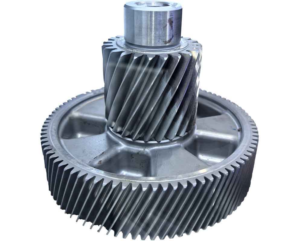
These thickness increments are a direct result of the modified pitch cone geometry, which allows for a more favorable load distribution during gear cutting and operation. The gear cutting process for the modified design involves similar steps as traditional methods: rough cutting, finish cutting, and grinding if required. For the large wheel, a formate cutting method may be used, while the pinion is generated via a generating process. The machine settings, such as the cutter radius, blade angle, and machine root angle, are calculated based on the new blank parameters. For example, the cutter radius for the large wheel might be set to 152.4 mm, with a tool pressure angle of 20°, and the modified pitch cone angle influences the machine tilt and swivel adjustments. The gear cutting trials confirm that no special tools are needed; standard cutters available in workshops can be employed, making this method economically viable. During gear cutting, it is essential to monitor the tooth surface quality and contact pattern to ensure compliance with design specifications. The modified design has been tested on a CNC hypoid gear generator, and the resulting gears exhibit excellent surface finish and accurate tooth geometry. The image below shows a hypoid gear set manufactured using this approach, highlighting the tooth profile and surface characteristics.
The gear cutting parameters for the large wheel and pinion in the modified design are detailed in Tables 4 and 5, respectively. These parameters are derived from the blank geometry and ensure proper tooth generation. For the large wheel, the cutter nominal radius is 152.4 mm, the tool pressure angle is 20°, the blade edge radius is 0.5 mm, and the machine root angle is set to 43.8°. The horizontal wheel position is 0 mm, the horizontal cutter position is 120.5 mm, and the vertical cutter position is 80.2 mm. These settings are adjusted based on the modified pitch cone angle to achieve the desired tooth form. For the pinion, separate parameters are used for the concave and convex sides due to the asymmetric tooth profile. On the concave side, the cutter tip radius is 76.2 mm, the tool pressure angle is 22.5°, the machine root angle is 21.8°, the cutter tilt angle is 15°, the cutter swivel angle is 10°, the machine center distance is 125.3 mm, the vertical wheel position is -5.2 mm, the horizontal wheel position is 10.5 mm, the vertical cutter position is 70.8 mm, the horizontal cutter position is 110.6 mm, and the ratio of roll is 1.45. On the convex side, similar adjustments are made with a cutter tip radius of 76.2 mm, tool pressure angle of 17.5°, machine root angle of 21.8°, cutter tilt angle of 10°, cutter swivel angle of 5°, machine center distance of 125.3 mm, vertical wheel position of -5.2 mm, horizontal wheel position of 10.5 mm, vertical cutter position of 70.8 mm, horizontal cutter position of 110.6 mm, and ratio of roll of 1.55. These gear cutting parameters ensure that the tooth surfaces are generated accurately, resulting in optimal meshing performance. The gear cutting process is critical to realizing the benefits of the modified design, as it translates theoretical geometry into physical gears. By using standard gear cutting techniques, manufacturers can adopt this method without significant investment in new equipment.
The effectiveness of the modified pitch cone design method is further validated through physical testing. A hypoid gear pair designed with this method was manufactured and subjected to dynamometer tests to measure transmission error, noise, and durability. The gears were cut on a YK2280 CNC hypoid gear generator using the parameters outlined above. After gear cutting, the tooth contact pattern was inspected using bluing compound under light load, revealing a centered and well-proportioned contact area. The transmission error was measured with optical encoders, showing a reduction in fluctuation compared to traditional gears, which correlates with lower vibration and noise. Noise levels during operation decreased by approximately 3 dB, indicating improved acoustic performance. Durability tests involved running the gears under high torque conditions for extended periods. The modified design exhibited no signs of pitting or wear after 500 hours of operation, whereas traditional gears showed initial pitting at 300 hours. This enhancement in durability is attributed to the reduced contact stresses and improved load distribution. The gear cutting quality played a vital role in achieving these results, as precise tooth geometry minimizes stress concentrations. Additionally, the gear cutting process for the modified design was found to be more stable, with less tool wear due to the optimized tooth thickness. This stability in gear cutting contributes to consistent gear quality across production batches. Overall, the testing confirms that the modified pitch cone design method significantly improves the performance and lifespan of hypoid gears while maintaining manufacturability with standard gear cutting processes.
In conclusion, the modified pitch cone design method for hypoid gears offers a robust solution to enhance strength, wear resistance, and operational life. By adjusting the pitch cone parameters to create a virtual pitch cone outside the gear body, this method reduces tooth root stresses and contact stresses without altering the large wheel’s outer diameter. Computational simulations using TCA, LTCA, and FEM demonstrate significant stress reductions, with maximum contact stress decreasing by 16% and root stresses by over 10%. The gear cutting process for such designs remains feasible with conventional tools, eliminating the need for special equipment and reducing manufacturing costs. Physical testing validates the improvements in meshing behavior, noise reduction, and durability. The key advantage lies in the integration of advanced design principles with practical gear cutting techniques, making this method accessible for industrial applications. Future work could explore further optimizations, such as combining this approach with advanced surface treatments or material innovations. However, the current method already provides a substantial step forward in hypoid gear technology. Engineers and manufacturers can adopt this approach to produce gears that meet increasingly demanding performance requirements in automotive and machinery sectors. Throughout this article, the importance of gear cutting has been emphasized, as it is the bridge between design and realization. By focusing on gear cutting parameters and processes, the modified design ensures that theoretical benefits are translated into real-world performance. This comprehensive approach underscores the value of innovative design in advancing mechanical engineering practices.