
I have frequently worked on long-stroke linear motion systems in which a rack and pinion gear drive is combined with a linear guide. When the stroke exceeds ten meters and the motion precision is not trivial, this arrangement is often one of the most practical solutions. In such a system, the linear guide primarily governs the straightness and geometric accuracy of the motion, while the positioning accuracy, reversal value, and related motion precision indices are mainly influenced by the machining and assembly accuracy of the rack and pinion gear, the guide, and the supporting structure. I have found that the influence of guide and base tolerances on straightness is relatively easy to analyze because the geometric relationship is direct. However, the quantitative influence of gear and rack accuracy, as well as the assembly deviations between the rack and pinion gear, on the final motion precision is much less obvious. I often need a clear calculation path that allows me to select components and assign tolerances before manufacturing. Therefore, I present a systematic analysis based on a typical rack and pinion gear transmission scheme. I use this scheme to show how machining and assembly tolerances propagate into positioning accuracy and reversal value.
The motion precision of a linear transmission system is usually evaluated by three indices: positioning accuracy, repeatability, and reversal value. Their definitions can vary slightly among products and standards. For machine tools and automatic inspection equipment, I usually refer to the principles of ISO 230-2 or equivalent standards for positioning accuracy and repeatability of numerically controlled axes. Among these indices, repeatability depends mainly on the stiffness and stability of the transmission system, the structure, and environmental variation. The dimensional accuracy of the transmission components does not directly determine repeatability. Therefore, I focus on the relationship between dimensional accuracy and the other two indices: positioning accuracy and reversal value.
| Motion precision index | Primary meaning | Main dependency in a rack and pinion gear system |
|---|---|---|
| Positioning accuracy | The difference between the actual position reached by the moving member and the target position commanded by the control system. | Tangential and radial errors of the rack and pinion gear, rack joint accuracy, and guide-related radial variation. |
| Repeatability | The closeness of agreement among repeated reaches of the same target position in the same direction. | Stiffness, stability, friction, backlash consistency, and environmental conditions. |
| Reversal value | The difference between the actual position reached when approaching a target from the positive direction and from the negative direction. | Meshing backlash, radial distance between the gear and rack, and related assembly tolerances. |
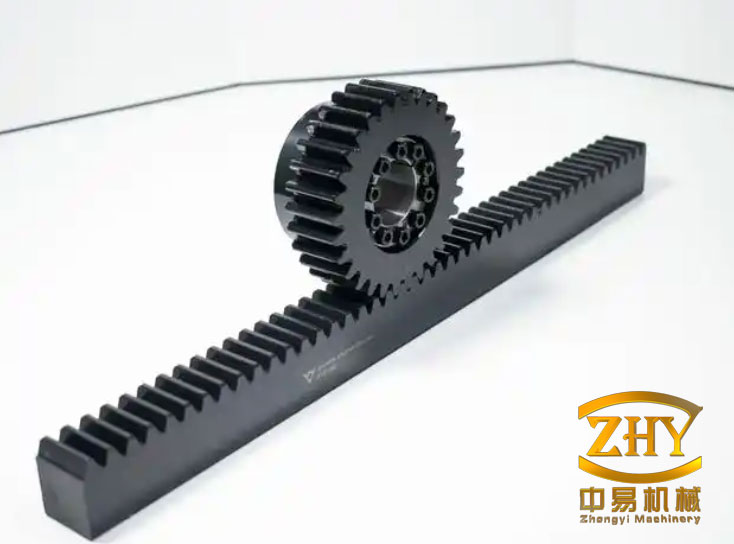
In my analysis, I treat the rack and pinion gear drive as a system of dimensional chains. Some errors act in the tangential direction, which is the direction of motion, and they can be added directly to the positioning error. Other errors act in the radial direction, which is perpendicular to the direction of motion. These radial errors must first be transformed into equivalent tangential errors before they can be included in the positioning error calculation. The radial distance variation between the gear and the rack is the key intermediate variable. I denote this radial variation as \(T_r\). When the gear and rack mesh, a radial deviation changes the effective contact point and therefore creates a tangential motion error. For a standard pressure angle \(\alpha\), the relationship is:
$$T_t = T_r \tan \alpha$$
Here, \(T_t\) is the equivalent tangential error caused by the radial error \(T_r\), and \(\alpha\) is the pressure angle of the rack and pinion gear. In the example I use later, the pressure angle is \(20^\circ\), so \(\tan \alpha = \tan 20^\circ \approx 0.36397\). This factor is important because it determines how strongly radial tolerances affect the final positioning accuracy. I often summarize this conversion in a table for different standard pressure angles.
| Pressure angle \(\alpha\) | \(\tan \alpha\) | Radial-to-tangential conversion factor |
|---|---|---|
| \(14.5^\circ\) | 0.2586 | A radial error of 0.100 mm creates about 0.026 mm tangential error. |
| \(20^\circ\) | 0.36397 | A radial error of 0.100 mm creates about 0.036 mm tangential error. |
| \(25^\circ\) | 0.4663 | A radial error of 0.100 mm creates about 0.047 mm tangential error. |
| \(30^\circ\) | 0.5774 | A radial error of 0.100 mm creates about 0.058 mm tangential error. |
For positioning accuracy, I identify two groups of influencing factors. The first group acts in the tangential direction and directly contributes to the positioning error. The second group acts in the radial direction and must be converted by the pressure angle before it contributes to the positioning error. Table 3 lists the tangential factors I consider in a typical rack and pinion gear drive.
| Number | Tangential factor | Symbol | Source of accuracy |
|---|---|---|---|
| 1 | Total cumulative pitch deviation of the pinion | \(F_{pp}\) | Gear accuracy grade |
| 2 | Total cumulative pitch tolerance of the rack | \(F_{pr}\) | Rack accuracy grade |
| 3 | Rack joint installation tolerance | \(T_e\) | Assembly method and joint tooling |
The radial factors that influence positioning accuracy are listed in Table 4. These factors do not act along the motion direction, but they change the radial distance between the gear and the rack during motion. Therefore, they indirectly create tangential positioning errors through the pressure angle relationship.
| Number | Radial factor | Symbol | Source of accuracy |
|---|---|---|---|
| 1 | Radial runout of the pinion | \(F_{rp}\) | Gear accuracy grade |
| 2 | Radial runout of the rack | \(F_{rr}\) | Rack accuracy grade |
| 3 | Distance tolerance between the guide and the rack | \(T_d\) | Machining of the supporting structure |
| 4 | Travel parallelism tolerance of the guide | \(T_p\) | Guide and slider selection |
In the radial dimensional chain, I also need to consider the distance between the guide and the gear center. However, in my positioning accuracy model, this distance is assumed to remain constant during motion. It therefore does not change the radial distance between the gear and the rack as the carriage travels. For this reason, I exclude its tolerance from the positioning accuracy radial error \(T_r\), although I include it later in the reversal value calculation. Using the statistical method for dimensional chains, I combine the independent radial errors as follows:
$$T_r = \sqrt{F_{rp}^2 + F_{rr}^2 + T_d^2 + T_p^2}$$
This equation gives the root-sum-square radial variation. I use it because the individual errors are assumed to be independent and random. If I were to use worst-case arithmetic addition, the result would be much larger and unnecessarily conservative for a long-stroke rack and pinion gear system. After obtaining \(T_r\), I convert it into the equivalent tangential error \(T_t\) using \(T_t = T_r \tan \alpha\). Then I combine all tangential contributions into the positioning error \(P\):
$$P = \sqrt{F_{pp}^2 + F_{pr}^2 + T_e^2 + T_t^2}$$
This equation is the core of my positioning accuracy estimate for a rack and pinion gear drive. I can use it during design to check whether a proposed combination of gear grade, rack grade, guide grade, and structural tolerances can meet the required positioning accuracy. If the calculated \(P\) is larger than the target, I can either improve one or more component tolerances or reduce the assembly tolerance. The sensitivity of \(P\) to each term can be evaluated by its squared contribution. I define the contribution ratio as:
$$C_i = \frac{T_i^2}{P^2} \times 100\%$$
This ratio tells me which error source dominates the final positioning error. I often use this calculation to avoid over-tolerancing components that have little effect. For example, if the rack joint tolerance \(T_e\) is large, it may dominate the positioning error even when the gear and rack grades are high. In contrast, if the guide travel parallelism \(T_p\) is very small, improving it further may have negligible benefit. This kind of contribution analysis is particularly useful for long-stroke rack and pinion gear systems because the number of rack joints can be large.
For the reversal value, the situation is different. Reversal value is caused by backlash in the rack and pinion gear mesh. A gear and rack pair must have suitable backlash to operate reliably. Without backlash, manufacturing deviations, assembly deviations, thermal expansion, and lubrication effects can cause excessive wear, noise, or even jamming. However, the necessary backlash creates a small lost motion when the drive reverses direction. This lost motion is the reversal value. In a rack and pinion gear drive, the backlash is more difficult to control than in a simple gear pair because the radial distance between the gear and the rack cannot be perfectly constant over a long stroke. The backlash also depends on operating speed, temperature, and lubrication, but I do not attempt to quantify those effects here. I focus on the geometric relationship between the radial distance and the reversal value.
When the pinion pitch circle and the rack pitch line have a radial distance \(d\), a clearance \(s\) appears on each side of the tooth. The total reversal value \(B\) is the sum of the clearances on both sides. From the tooth geometry, I obtain:
$$B = 2s = 2d \tan \alpha$$
This equation shows that the reversal value is directly proportional to the radial distance \(d\) and to \(\tan \alpha\). For a given pressure angle, controlling the radial distance is the key to controlling the reversal value. A minimum backlash \(B_{min}\) is required to avoid jamming and excessive wear. A maximum reversal value \(B_{max}\) is usually specified by the motion requirement. Therefore, the design must satisfy:
$$B_{min} \le B \le B_{max}$$
Substituting \(B = 2d \tan \alpha\), I can determine the allowable range of the radial distance \(d\):
$$d_{min} = \frac{B_{min}}{2 \tan \alpha}$$
$$d_{max} = \frac{B_{max}}{2 \tan \alpha}$$
In the design of a rack and pinion gear system, I also need to include the distance between the guide and the gear center. Let \(L_0\) be the nominal radial distance between the gear pitch circle and the rack pitch line, and let \(T_r\) be the total radial variation. The actual radial distance during motion lies approximately in the interval:
$$L_0 – \frac{T_r}{2} \le d \le L_0 + \frac{T_r}{2}$$
To ensure that the reversal value remains within the required range, I must satisfy:
$$L_0 + \frac{T_r}{2} \le d_{max}$$
$$L_0 – \frac{T_r}{2} \ge d_{min}$$
For the reversal value calculation, the radial variation \(T_r\) includes five independent contributions. In addition to the four terms used for positioning accuracy, I must include the tolerance \(T_c\) of the distance between the guide and the gear center. Although this distance is constant during a single motion, it affects the absolute radial distance between the gear and the rack, and therefore it affects the reversal value. The combined radial variation for reversal value is:
$$T_r = \sqrt{F_{rp}^2 + F_{rr}^2 + T_d^2 + T_p^2 + T_c^2}$$
I summarize the factors affecting the reversal value in Table 5. This table is useful because it distinguishes between factors that also affect positioning accuracy and factors that are specific to the reversal value calculation.
| Number | Radial factor | Symbol | Affects positioning accuracy? | Affects reversal value? |
|---|---|---|---|---|
| 1 | Pinion radial runout | \(F_{rp}\) | Yes | Yes |
| 2 | Rack radial runout | \(F_{rr}\) | Yes | Yes |
| 3 | Guide-to-rack distance tolerance | \(T_d\) | Yes | Yes |
| 4 | Guide travel parallelism | \(T_p\) | Yes | Yes |
| 5 | Guide-to-gear-center distance tolerance | \(T_c\) | No in my model | Yes |
Now I apply these equations to a representative rack and pinion gear design. The example is a long-stroke linear motion system with a module of 3 mm. The pinion has 22 teeth. The rack has a module of 3 mm and 108 teeth per segment. Both the pinion and the rack are straight-tooth components with a pressure angle of \(20^\circ\). The required unidirectional positioning accuracy is 0.10 mm. The required reversal value is 0.15 mm. I ignore the errors of the motor, reducer, and other transmission components in this calculation so that I can focus on the rack and pinion gear and the supporting structure.
| Parameter | Value | Unit |
|---|---|---|
| Pinion module | 3 | mm |
| Pinion number of teeth | 22 | — |
| Rack module | 3 | mm |
| Rack teeth per segment | 108 | — |
| Pressure angle | 20 | degree |
| Required unidirectional positioning accuracy | 0.10 | mm |
| Required reversal value | 0.15 | mm |
For the pinion, I select accuracy grade 6. From the relevant gear accuracy standard, I obtain a radial runout \(F_{rp} = 0.021\) mm and a total cumulative pitch deviation \(F_{pp} = 0.027\) mm. For the rack, I also select accuracy grade 6. I obtain a radial runout \(F_{rr} = 0.028\) mm and a total cumulative pitch tolerance \(F_{pr} = 0.034\) mm. For the linear guide, I select a high-precision H-grade slider and rail. The travel parallelism tolerance is \(T_p = 0.016\) mm. At this stage, I tentatively set the structural distance tolerance between the guide and the rack to \(T_d = 0.100\) mm. I also assume that the rack joints are assembled with a dedicated high-precision jointing tool. Based on the adjustment accuracy of this tool, I set the rack joint tolerance to \(T_e = 0.050\) mm. These selections are summarized in Table 7.
| Component or dimension | Symbol | Selected value (mm) | Basis |
|---|---|---|---|
| Pinion radial runout | \(F_{rp}\) | 0.021 | Grade 6 pinion |
| Pinion total cumulative pitch deviation | \(F_{pp}\) | 0.027 | Grade 6 pinion |
| Rack radial runout | \(F_{rr}\) | 0.028 | Grade 6 rack |
| Rack total cumulative pitch tolerance | \(F_{pr}\) | 0.034 | Grade 6 rack |
| Guide travel parallelism | \(T_p\) | 0.016 | H-grade guide |
| Guide-to-rack distance tolerance | \(T_d\) | 0.100 | Tentative design tolerance |
| Rack joint tolerance | \(T_e\) | 0.050 | Jointing tool accuracy |
With these values, I first calculate the radial error \(T_r\) for positioning accuracy. I use the equation that excludes \(T_c\):
$$T_r = \sqrt{F_{rp}^2 + F_{rr}^2 + T_d^2 + T_p^2}$$
$$T_r = \sqrt{0.021^2 + 0.028^2 + 0.100^2 + 0.016^2}$$
$$T_r = \sqrt{0.000441 + 0.000784 + 0.010000 + 0.000256}$$
$$T_r = \sqrt{0.011481} \approx 0.107 \text{ mm}$$
Next, I convert this radial error into an equivalent tangential error using the pressure angle:
$$T_t = T_r \tan \alpha = 0.107 \times \tan 20^\circ \approx 0.107 \times 0.36397 \approx 0.039 \text{ mm}$$
Now I calculate the unidirectional positioning error \(P\) by combining the tangential errors:
$$P = \sqrt{F_{pp}^2 + F_{pr}^2 + T_e^2 + T_t^2}$$
$$P = \sqrt{0.027^2 + 0.034^2 + 0.050^2 + 0.039^2}$$
$$P = \sqrt{0.000729 + 0.001156 + 0.002500 + 0.001521}$$
$$P = \sqrt{0.005906} \approx 0.077 \text{ mm}$$
The calculated positioning error is about 0.077 mm, which is less than the required 0.10 mm. Therefore, the selected component grades and the tentative structural tolerance satisfy the unidirectional positioning accuracy requirement. To understand which error source dominates, I calculate the squared contribution of each term in the positioning error equation. Table 8 shows the results.
| Error term | Squared value (mm\(^2\)) | Contribution to \(P^2\) (%) |
|---|---|---|
| \(F_{pp}^2\) | 0.000729 | 12.3 |
| \(F_{pr}^2\) | 0.001156 | 19.6 |
| \(T_e^2\) | 0.002500 | 42.3 |
| \(T_t^2\) | 0.001521 | 25.8 |
| Total \(P^2\) | 0.005906 | 100.0 |
The table shows that the rack joint tolerance \(T_e\) is the largest single contributor to the positioning error. This is a common result in long-stroke rack and pinion gear systems. The second largest contribution comes from the radial error converted into tangential error \(T_t\). Among the radial terms, the guide-to-rack distance tolerance \(T_d = 0.100\) mm is the dominant one. Therefore, if I need to improve positioning accuracy further, I should first reduce the rack joint tolerance and then tighten the guide-to-rack distance tolerance. Improving the pinion grade alone would provide only a limited benefit.
Next, I analyze the reversal value. I require the reversal value to be no less than 0.05 mm to avoid jamming and excessive wear, and no greater than 0.15 mm to meet the motion requirement. I set the minimum backlash to \(B_{min} = 0.05\) mm and the maximum reversal value to \(B_{max} = 0.15\) mm. Using the pressure angle, I calculate the allowable radial distance range:
$$d_{min} = \frac{B_{min}}{2 \tan \alpha} = \frac{0.05}{2 \times 0.36397} \approx 0.068 \text{ mm}$$
$$d_{max} = \frac{B_{max}}{2 \tan \alpha} = \frac{0.15}{2 \times 0.36397} \approx 0.206 \text{ mm}$$
Thus, the actual radial distance between the pinion pitch circle and the rack pitch line must remain between approximately 0.068 mm and 0.206 mm. I design the nominal radial distance as \(L_0 = 0.13\) mm. I also need the total radial variation \(T_r\) for the reversal value calculation to be small enough. From the inequality:
$$L_0 + \frac{T_r}{2} \le d_{max}$$
$$L_0 – \frac{T_r}{2} \ge d_{min}$$
I obtain:
$$T_r \le 2(d_{max} – L_0) = 2(0.206 – 0.13) = 0.152 \text{ mm}$$
$$T_r \le 2(L_0 – d_{min}) = 2(0.13 – 0.068) = 0.124 \text{ mm}$$
The more restrictive condition is \(T_r \le 0.124\) mm. I set a design target of \(T_r \le 0.12\) mm for the reversal value calculation. Now I include the guide-to-gear-center distance tolerance \(T_c\). The radial variation for reversal value is:
$$T_r = \sqrt{F_{rp}^2 + F_{rr}^2 + T_d^2 + T_p^2 + T_c^2}$$
I substitute the known values and the target \(T_r \le 0.12\) mm:
$$0.12 \ge \sqrt{0.021^2 + 0.028^2 + 0.100^2 + 0.016^2 + T_c^2}$$
$$0.12^2 \ge 0.000441 + 0.000784 + 0.010000 + 0.000256 + T_c^2$$
$$0.014400 \ge 0.011481 + T_c^2$$
$$T_c^2 \le 0.002919$$
$$T_c \le 0.054 \text{ mm}$$
This result shows that if I keep \(T_d = 0.100\) mm, the guide-to-gear-center distance tolerance \(T_c\) must be no larger than about 0.054 mm. However, the guide-to-gear-center distance is usually a larger structural dimension than the guide-to-rack distance. In many machines, it is more difficult to hold a tight tolerance on a larger dimension. Therefore, I adjust the two tolerances. I relax \(T_c\) to 0.100 mm and tighten \(T_d\) to 0.050 mm. This allocation is more compatible with typical machining practice because the smaller dimension receives the tighter tolerance. I then recheck the reversal value. The new radial variation is:
$$T_r = \sqrt{0.021^2 + 0.028^2 + 0.050^2 + 0.016^2 + 0.100^2}$$
$$T_r = \sqrt{0.000441 + 0.000784 + 0.002500 + 0.000256 + 0.010000}$$
$$T_r = \sqrt{0.013981} \approx 0.118 \text{ mm}$$
Now I calculate the minimum and maximum reversal values using the nominal radial distance \(L_0 = 0.13\) mm and the adjusted radial variation \(T_r \approx 0.118\) mm:
$$B_{min} = 2 \left( L_0 – \frac{T_r}{2} \right) \tan \alpha$$
$$B_{min} = 2 \left( 0.13 – 0.059 \right) \times 0.36397$$
$$B_{min} = 2 \times 0.071 \times 0.36397 \approx 0.052 \text{ mm}$$
$$B_{max} = 2 \left( L_0 + \frac{T_r}{2} \right) \tan \alpha$$
$$B_{max} = 2 \left( 0.13 + 0.059 \right) \times 0.36397$$
$$B_{max} = 2 \times 0.189 \times 0.36397 \approx 0.138 \text{ mm}$$
The calculated reversal value range is approximately 0.052 mm to 0.138 mm. This satisfies both the minimum backlash requirement of 0.05 mm and the maximum reversal value requirement of 0.15 mm. Table 9 summarizes the reversal value calculation before and after the tolerance adjustment.
| Quantity | Initial allocation | Adjusted allocation |
|---|---|---|
| \(T_d\) (mm) | 0.100 | 0.050 |
| \(T_c\) (mm) | 0.054 maximum | 0.100 |
| \(T_r\) for reversal value (mm) | 0.120 | 0.118 |
| \(B_{min}\) (mm) | 0.051 | 0.052 |
| \(B_{max}\) (mm) | 0.138 | 0.138 |
| Requirement satisfied? | Yes | Yes |
After adjusting the tolerances, I also recheck the positioning accuracy because \(T_d\) has changed from 0.100 mm to 0.050 mm. The positioning accuracy radial variation becomes:
$$T_r = \sqrt{0.021^2 + 0.028^2 + 0.050^2 + 0.016^2}$$
$$T_r = \sqrt{0.000441 + 0.000784 + 0.002500 + 0.000256}$$
$$T_r = \sqrt{0.003981} \approx 0.063 \text{ mm}$$
$$T_t = 0.063 \times 0.36397 \approx 0.023 \text{ mm}$$
$$P = \sqrt{0.027^2 + 0.034^2 + 0.050^2 + 0.023^2}$$
$$P = \sqrt{0.000729 + 0.001156 + 0.002500 + 0.000529}$$
$$P = \sqrt{0.004914} \approx 0.070 \text{ mm}$$
The adjusted positioning error is about 0.070 mm, which is even better than the initial estimate of 0.077 mm and remains well within the 0.10 mm requirement. This demonstrates that a careful reallocation of structural tolerances can improve both manufacturability and motion precision. In my experience, this kind of iteration is essential in the design of a rack and pinion gear drive for long-stroke applications.
Table 10 presents the final design values and the resulting motion precision. I use this table as a summary for the design review.
| Item | Symbol | Final value | Unit |
|---|---|---|---|
| Pinion radial runout | \(F_{rp}\) | 0.021 | mm |
| Pinion total cumulative pitch deviation | \(F_{pp}\) | 0.027 | mm |
| Rack radial runout | \(F_{rr}\) | 0.028 | mm |
| Rack total cumulative pitch tolerance | \(F_{pr}\) | 0.034 | mm |
| Guide travel parallelism | \(T_p\) | 0.016 | mm |
| Guide-to-rack distance tolerance | \(T_d\) | 0.050 | mm |
| Guide-to-gear-center distance tolerance | \(T_c\) | 0.100 | mm |
| Rack joint tolerance | \(T_e\) | 0.050 | mm |
| Nominal radial distance | \(L_0\) | 0.130 | mm |
| Positioning error | \(P\) | 0.070 | mm |
| Minimum reversal value | \(B_{min}\) | 0.052 | mm |
| Maximum reversal value | \(B_{max}\) | 0.138 | mm |
I can also express the key relationships in a more general form. For a rack and pinion gear drive, the positioning error \(P\) can be written as a function of the individual tolerances:
$$P = \sqrt{F_{pp}^2 + F_{pr}^2 + T_e^2 + \left( \tan \alpha \sqrt{F_{rp}^2 + F_{rr}^2 + T_d^2 + T_p^2} \right)^2}$$
This single equation combines the tangential and radial contributions. It is convenient for sensitivity analysis. I can differentiate \(P\) with respect to each tolerance to estimate the effect of a small change. For example, the sensitivity with respect to the rack joint tolerance \(T_e\) is:
$$\frac{\partial P}{\partial T_e} = \frac{T_e}{P}$$
At the initial design point, \(T_e = 0.050\) mm and \(P = 0.077\) mm, so the sensitivity is about 0.65. This means that a 0.010 mm reduction in \(T_e\) would reduce \(P\) by roughly 0.0065 mm, assuming all other terms remain constant. Similarly, the sensitivity with respect to \(T_d\) is:
$$\frac{\partial P}{\partial T_d} = \frac{\tan^2 \alpha \, T_d}{P}$$
This expression shows that \(T_d\) affects \(P\) through the square of the pressure angle factor. Because \(\tan^2 20^\circ \approx 0.1325\), the influence of \(T_d\) on \(P\) is smaller than its direct value might suggest. This is why the initial \(T_d = 0.100\) mm did not cause \(P\) to exceed 0.10 mm. However, \(T_d\) also affects the reversal value directly, so it cannot be relaxed without considering backlash.
For the reversal value, the sensitivity with respect to the radial distance is:
$$\frac{\partial B}{\partial d} = 2 \tan \alpha$$
With \(\alpha = 20^\circ\), this sensitivity is about 0.728. Therefore, a radial distance variation of 0.010 mm changes the reversal value by about 0.0073 mm. This is a useful rule of thumb. If the total radial variation \(T_r\) is 0.118 mm, the reversal value range is approximately \(0.118 \times 0.728 \approx 0.086\) mm wide. The nominal reversal value is \(2 L_0 \tan \alpha \approx 2 \times 0.13 \times 0.36397 \approx 0.095\) mm. The minimum and maximum values are then about \(0.095 \pm 0.043\) mm, which gives 0.052 mm and 0.138 mm, matching the detailed calculation.
In addition to the numerical example, I consider several practical design rules that I have found useful for rack and pinion gear systems. First, the rack joint tolerance \(T_e\) is often the largest contributor to positioning error in a long-stroke system. I therefore specify a dedicated jointing tool and a strict assembly procedure. If the rack segments are simply butted together without a precision tool, \(T_e\) can easily exceed 0.10 mm, which may consume the entire positioning error budget. Second, the guide-to-rack distance tolerance \(T_d\) should be assigned to the structural surface that is easiest to machine accurately. In many designs, this is a machined shoulder or a precision spacer. Third, the guide-to-gear-center distance tolerance \(T_c\) is usually less critical for positioning accuracy but very important for reversal value. I often use an adjustable eccentric mounting for the pinion so that the nominal radial distance \(L_0\) and the backlash can be fine-tuned during assembly. Fourth, the guide travel parallelism \(T_p\) should be compatible with the required straightness. A very tight \(T_p\) may be unnecessary if the positioning accuracy target is moderate, but it becomes important when the required positioning accuracy is below 0.05 mm.
I also note that the statistical root-sum-square method assumes that the errors are independent and normally distributed. In reality, some errors may be correlated. For example, the rack joint tolerance may have a systematic component if the joints are assembled in the same way. If I suspect correlation, I can use a more conservative method or add a correlation factor. However, for the conceptual design stage, the root-sum-square method provides a reasonable balance between accuracy and simplicity. I use it to compare design alternatives and to identify the dominant error sources.
Another important consideration is temperature. A long rack and pinion gear system can experience significant thermal expansion. If the rack is mounted on a structure with a different coefficient of thermal expansion than the rack material, the effective pitch of the rack can change. This effect is not included in the dimensional chain equations above because it is not a fixed machining tolerance. However, I can estimate it separately. For a steel rack with a coefficient of thermal expansion of about \(11.7 \times 10^{-6}\) per degree Celsius, a temperature change of \(10^\circ\)C over a 10 m length produces an expansion of about 1.17 mm. This is much larger than the positioning accuracy target of 0.10 mm. Therefore, for high-precision long-stroke systems, I must either control the temperature, use a compensation system, or mount the rack in a way that allows thermal expansion without affecting the mesh. This is a critical point that is sometimes overlooked in the early design stage.
I also consider the effect of the pressure angle on the conversion between radial and tangential errors. A larger pressure angle increases \(\tan \alpha\), so a given radial error produces a larger tangential error and a larger reversal value for the same radial distance. However, a larger pressure angle can also increase the load capacity and reduce the risk of undercut. In my design, I selected \(20^\circ\), which is a common compromise. If I needed to reduce the sensitivity to radial errors, I might consider a smaller pressure angle, but I would need to check the strength and contact ratio. Table 11 shows the conversion factors for several pressure angles.
| Pressure angle \(\alpha\) | \(\tan \alpha\) | \(2 \tan \alpha\) | Effect on reversal value for \(d = 0.13\) mm |
|---|---|---|---|
| \(14.5^\circ\) | 0.2586 | 0.5172 | \(B \approx 0.067\) mm |
| \(20^\circ\) | 0.36397 | 0.72794 | \(B \approx 0.095\) mm |
| \(25^\circ\) | 0.4663 | 0.9326 | \(B \approx 0.121\) mm |
| \(30^\circ\) | 0.5774 | 1.1548 | \(B \approx 0.150\) mm |
The table shows that the pressure angle has a strong influence on the reversal value. If I had selected a \(30^\circ\) pressure angle, the nominal reversal value with the same radial distance would already be about 0.150 mm, leaving no margin for variation. Therefore, the pressure angle must be considered together with the backlash requirement. In my example, \(20^\circ\) provides a good balance.
I also examine the effect of the pinion diameter and the number of teeth. The pinion diameter is \(d = m z = 3 \times 22 = 66\) mm. The pitch circumference is \(\pi d \approx 207.3\) mm. The pitch per tooth is \(\pi m = 9.425\) mm. These values are not directly in the error equations, but they influence the measurement and the sensitivity of the angular errors. For example, a small angular error \(\Delta \theta\) at the pinion produces a linear error at the pitch circle of \(r \Delta \theta\), where \(r = d/2 = 33\) mm. If the pinion has a total cumulative pitch deviation \(F_{pp} = 0.027\) mm, this corresponds to an equivalent angular error of \(F_{pp}/r \approx 0.027/33 \approx 0.000818\) rad, or about 0.047 degrees. This helps me understand the relationship between linear and angular accuracy. The rack pitch error \(F_{pr} = 0.034\) mm is already a linear error along the rack. The rack joint tolerance \(T_e = 0.050\) mm is also a linear error. Therefore, the tangential error components are directly comparable.
For the radial components, I can also express them as equivalent angular errors. The radial runout of the pinion \(F_{rp} = 0.021\) mm creates a tangential error of \(F_{rp} \tan \alpha \approx 0.021 \times 0.36397 \approx 0.0076\) mm. The radial runout of the rack \(F_{rr} = 0.028\) mm creates a tangential error of about 0.0102 mm. The guide-related radial errors \(T_d = 0.050\) mm and \(T_p = 0.016\) mm create tangential errors of about 0.0182 mm and 0.0058 mm, respectively. These values are smaller than the rack joint tolerance \(T_e = 0.050\) mm, but they are not negligible. In the initial design with \(T_d = 0.100\) mm, the guide-to-rack distance contributed about 0.0364 mm tangential error, which was larger than the pinion and rack radial runout combined. This shows why the structural tolerance \(T_d\) deserves careful attention.
I summarize the equivalent tangential contributions in Table 12. This table is useful for comparing error sources on a common basis.
| Error source | Original type | Value (mm) | Equivalent tangential error (mm) |
|---|---|---|---|
| Pinion cumulative pitch deviation \(F_{pp}\) | Tangential | 0.027 | 0.027 |
| Rack cumulative pitch tolerance \(F_{pr}\) | Tangential | 0.034 | 0.034 |
| Rack joint tolerance \(T_e\) | Tangential | 0.050 | 0.050 |
| Pinion radial runout \(F_{rp}\) | Radial | 0.021 | 0.0076 |
| Rack radial runout \(F_{rr}\) | Radial | 0.028 | 0.0102 |
| Guide-to-rack distance \(T_d\) (initial) | Radial | 0.100 | 0.0364 |
| Guide travel parallelism \(T_p\) | Radial | 0.016 | 0.0058 |
After the tolerance adjustment, the guide-to-rack distance \(T_d\) is reduced to 0.050 mm, so its equivalent tangential error becomes about 0.0182 mm. The total radial error for positioning accuracy becomes \(T_r = 0.063\) mm, and the equivalent tangential error becomes 0.023 mm. The positioning error is then 0.070 mm. This is a comfortable margin below the 0.10 mm requirement. I can use this margin to absorb other effects such as thermal expansion, elastic deformation under load, and control system errors.
I also consider the effect of the rack joint tolerance \(T_e\) on the reversal value. The reversal value is caused by backlash, which is a radial phenomenon, but the rack joint tolerance is a tangential phenomenon. Therefore, \(T_e\) does not directly enter the reversal value equation. However, a large \(T_e\) may indicate poor rack alignment, which could also affect the radial distance between the gear and the rack. In my model, I treat \(T_e\) as a separate tangential error for positioning accuracy and do not include it in the radial variation for reversal value. This is a simplification, but it is consistent with the dimensional chain approach. If the rack joints are poorly aligned, the rack may have a local step that changes the effective radial distance. In such a case, I would need to add an additional radial term to the reversal value equation. I therefore recommend that the rack joint tolerance be kept small not only for positioning accuracy but also for smooth meshing.
Another practical point is the measurement of the reversal value. In a rack and pinion gear drive, the reversal value can be measured by approaching a target position from both directions and recording the difference. This measurement should be performed at several positions along the stroke because the backlash may vary due to rack pitch errors, guide parallelism, and structural deflection. I usually measure at the beginning, middle, and end of the stroke, and also at each rack joint. If the reversal value varies significantly, I investigate whether the variation is caused by the rack joint, the guide alignment, or the pinion mounting. The equations in this article can help me interpret the measurements and identify the root cause.
For the positioning accuracy measurement, I use a laser interferometer or a linear encoder with sufficient resolution. The measurement should follow a standard procedure such as ISO 230-2. I approach each target position from the same direction to obtain the unidirectional positioning error. I repeat the measurement several times to separate the systematic error from random scatter. The systematic error is compared with the calculated \(P\). If the measured error is larger than the calculated value, I check for additional error sources such as thermal drift, elastic deformation, or control system following error. If the measured error is smaller, the design has extra margin that can be used for other purposes.
In my experience, the most difficult part of achieving high motion precision in a rack and pinion gear system is not the selection of the gear and rack themselves. Modern gear and rack manufacturing can provide very accurate components. The difficulty lies in the structural tolerances and the assembly process. The guide-to-rack distance, the guide-to-gear-center distance, and the rack joint alignment are all influenced by the machine frame, the mounting surfaces, and the assembly sequence. These factors are often more challenging to control than the gear tooth accuracy. Therefore, I always recommend that the design team consider the assembly method at the same time as the component selection. For example, if the guide-to-rack distance is adjusted with shims, the shim thickness should be selected after measuring the actual guide position. If the pinion is mounted on an eccentric bushing, the backlash can be adjusted after the rack is installed. These adjustable features can greatly reduce the required machining tolerances and improve the final motion precision.
I also consider the stiffness of the system. The equations above assume that the structural deflection under load is negligible. In reality, the pinion shaft, the bearing housing, the carriage, and the machine frame all deflect under the transmitted force. This deflection can cause a change in the radial distance between the gear and the rack, which in turn changes the backlash and the positioning error. For high-precision applications, I estimate the deflection and compare it with the radial tolerance budget. If the deflection is significant, I increase the stiffness of the components or use a preload to reduce the effect. The rack and pinion gear mesh itself also has a stiffness that depends on the contact ratio and the tooth deflection. This is a more advanced topic, but it should not be ignored in a complete design.
I now return to the general design procedure. I can summarize the steps I follow when designing a rack and pinion gear drive for a specified motion precision.
- Define the required unidirectional positioning accuracy \(P_{req}\) and the required reversal value range \(B_{min}\) to \(B_{max}\).
- Select the pressure angle \(\alpha\). Calculate \(\tan \alpha\).
- Select tentative accuracy grades for the pinion and rack. Obtain \(F_{pp}\), \(F_{rp}\), \(F_{pr}\), and \(F_{rr}\).
- Select a guide grade. Obtain \(T_p\).
- Estimate a tentative guide-to-rack distance tolerance \(T_d\) based on the machining capability.
- Estimate the rack joint tolerance \(T_e\) based on the jointing tool and assembly method.
- Calculate the radial error for positioning accuracy using \(T_r = \sqrt{F_{rp}^2 + F_{rr}^2 + T_d^2 + T_p^2}\).
- Convert to tangential error using \(T_t = T_r \tan \alpha\).
- Calculate the positioning error using \(P = \sqrt{F_{pp}^2 + F_{pr}^2 + T_e^2 + T_t^2}\).
- If \(P > P_{req}\), reduce the dominant tolerance and repeat the calculation.
- Calculate the allowable radial distance range for the reversal value: \(d_{min} = B_{min}/(2 \tan \alpha)\) and \(d_{max} = B_{max}/(2 \tan \alpha)\).
- Choose a nominal radial distance \(L_0\) between \(d_{min}\) and \(d_{max}\).
- Determine the maximum allowable radial variation \(T_r\) for the reversal value from \(L_0 + T_r/2 \le d_{max}\) and \(L_0 – T_r/2 \ge d_{min}\).
- Calculate the required guide-to-gear-center distance tolerance \(T_c\) using \(T_r = \sqrt{F_{rp}^2 + F_{rr}^2 + T_d^2 + T_p^2 + T_c^2}\).
- If \(T_c\) is too tight for manufacturing, adjust \(T_d\) and \(T_c\) to achieve a better balance.
- Recheck both positioning accuracy and reversal value with the final tolerance allocation.
- Document the final tolerances and the assembly adjustment method.
I find that this procedure provides a clear path from the motion requirement to the component and structural tolerances. It also helps me communicate with the manufacturing and assembly teams because it shows which tolerances are critical and which are less important. In the example above, the rack joint tolerance \(T_e\) and the guide-to-rack distance \(T_d\) were the most important factors. The pinion and rack radial runouts were less significant. The guide travel parallelism \(T_p\) was also relatively small. This information allows the team to focus their attention on the critical items.
I also note that the equations can be used in reverse. If the manufacturing team tells me that a certain tolerance is difficult to achieve, I can calculate the effect on the final motion precision and decide whether the requirement can be relaxed or whether another tolerance must be tightened to compensate. For example, if \(T_e\) cannot be held to 0.050 mm and must be increased to 0.080 mm, I can calculate the new positioning error. The tangential error budget would increase. I would then need to reduce another tangential error, such as \(F_{pr}\) or \(T_t\), to keep \(P\) below 0.10 mm. This kind of trade-off analysis is very useful during design reviews.
Let me illustrate this trade-off with a quick calculation. Suppose \(T_e\) increases from 0.050 mm to 0.080 mm while all other values remain at the initial design point except that \(T_d\) is already adjusted to 0.050 mm. The positioning error becomes:
$$P = \sqrt{0.027^2 + 0.034^2 + 0.080^2 + 0.023^2}$$
$$P = \sqrt{0.000729 + 0.001156 + 0.006400 + 0.000529}$$
$$P = \sqrt{0.008814} \approx 0.094 \text{ mm}$$
This is still below 0.10 mm, but the margin is smaller. If \(T_e\) increases to 0.100 mm, the positioning error becomes:
$$P = \sqrt{0.027^2 + 0.034^2 + 0.100^2 + 0.023^2}$$
$$P = \sqrt{0.000729 + 0.001156 + 0.010000 + 0.000529}$$
$$P = \sqrt{0.012414} \approx 0.111 \text{ mm}$$
This exceeds the 0.10 mm requirement. Therefore, the rack joint tolerance is a critical parameter. I would not allow it to increase to 0.100 mm without compensating elsewhere. This calculation confirms the importance of the jointing tool and the assembly procedure.
Similarly, I can analyze the effect of the guide-to-rack distance tolerance \(T_d\). If \(T_d\) increases from 0.050 mm to 0.080 mm, the radial error for positioning accuracy becomes:
$$T_r = \sqrt{0.021^2 + 0.028^2 + 0.080^2 + 0.016^2}$$
$$T_r = \sqrt{0.000441 + 0.000784 + 0.006400 + 0.000256}$$
$$T_r = \sqrt{0.007881} \approx 0.089 \text{ mm}$$
$$T_t = 0.089 \times 0.36397 \approx 0.032 \text{ mm}$$
$$P = \sqrt{0.027^2 + 0.034^2 + 0.050^2 + 0.032^2}$$
$$P = \sqrt{0.000729 + 0.001156 + 0.002500 + 0.001024}$$
$$P = \sqrt{0.005409} \approx 0.074 \text{ mm}$$
The positioning error remains below 0.10 mm. However, the reversal value would also be affected because \(T_d\) appears in the reversal value radial variation. If \(T_d = 0.080\) mm and \(T_c = 0.100\) mm, the reversal value radial variation becomes:
$$T_r = \sqrt{0.021^2 + 0.028^2 + 0.080^2 + 0.016^2 + 0.100^2}$$
$$T_r = \sqrt{0.000441 + 0.000784 + 0.006400 + 0.000256 + 0.010000}$$
$$T_r = \sqrt{0.017881} \approx 0.134 \text{ mm}$$
Then the reversal value range becomes:
$$B_{min} = 2 \left( 0.13 – 0.067 \right) \times 0.36397 \approx 0.046 \text{ mm}$$
$$B_{max} = 2 \left( 0.13 + 0.067 \right) \times 0.36397 \approx 0.143 \text{ mm}$$
The minimum reversal value is now about 0.046 mm, which is slightly below the desired minimum of 0.05 mm. This means that if \(T_d\) is relaxed to 0.080 mm, the backlash might become too small, increasing the risk of jamming or excessive wear. Therefore, \(T_d\) cannot be relaxed indefinitely even if the positioning accuracy remains acceptable. This example shows the importance of checking both positioning accuracy and reversal value together.
I can also consider the effect of the nominal radial distance \(L_0\). If I increase \(L_0\), the nominal reversal value increases. For example, if \(L_0 = 0.15\) mm instead of 0.13 mm, the nominal reversal value becomes \(2 \times 0.15 \times 0.36397 \approx 0.109\) mm. The minimum and maximum values with \(T_r = 0.118\) mm become:
$$B_{min} = 2 \left( 0.15 – 0.059 \right) \times 0.36397 \approx 0.066 \text{ mm}$$
$$B_{max} = 2 \left( 0.15 + 0.059 \right) \times 0.36397 \approx 0.152 \text{ mm}$$
The maximum reversal value would exceed 0.15 mm. Therefore, \(L_0\) must be chosen carefully to keep the entire reversal value range within the specification. In this case, \(L_0 = 0.13\) mm is a good choice because it provides a minimum of about 0.052 mm and a maximum of about 0.138 mm, leaving margin on both sides.
I also note that the minimum backlash \(B_{min} = 0.05\) mm is an empirical value. In some applications, a smaller minimum backlash may be acceptable if the lubrication is excellent and the thermal expansion is controlled. In other applications, a larger minimum backlash may be required to ensure reliable operation. The designer should consider the operating conditions, the load, the speed, and the environment. The equations in this article can be used with any chosen \(B_{min}\) and \(B_{max}\).
For a rack and pinion gear system with a very long stroke, the number of rack joints can be large. Each joint introduces a potential tangential error \(T_e\). If there are \(n\) joints, the total joint error may accumulate. In my statistical model, I assume that the joint errors are independent, so the combined joint error is \(T_e \sqrt{n}\). If the joint errors are systematic, the combined error could be \(n T_e\). Therefore, the assembly method is critical. I usually specify that the rack joints be staggered or that the joint error be measured and compensated. In some systems, the rack is supplied in long segments to reduce the number of joints. This is a design decision that affects both cost and accuracy.
I can express the combined joint error as:
$$T_{e,total} = T_e \sqrt{n}$$
For example, if \(T_e = 0.050\) mm and there are 5 joints, the combined joint error is \(0.050 \sqrt{5} \approx 0.112\) mm. This is larger than the single joint tolerance and could dominate the positioning error. Therefore, for a long stroke, I must either reduce \(T_e\) or reduce the number of joints. If the rack is supplied in 2 m segments and the stroke is 10 m, there are 5 joints. The combined error is significant. If the rack is supplied in 3 m segments, there are 3 joints, and the combined error is \(0.050 \sqrt{3} \approx 0.087\) mm. This is still significant but smaller. The designer should include the number of joints in the error budget. In my example, I assumed a single joint or a small number of joints. For a long stroke, the calculation should be repeated with the actual number of joints.
I also consider the effect of the rack pitch error \(F_{pr}\). The total cumulative pitch tolerance of the rack is specified over a certain length. If the rack is made of multiple segments, the cumulative pitch error can accumulate over the entire stroke. The manufacturer usually specifies the pitch error per segment or per meter. I must ensure that the total pitch error over the full stroke is within the budget. If the rack segments are not matched, the cumulative error can be larger than the sum of the individual errors. Therefore, I prefer to purchase rack segments from the same manufacturer and to specify the matching requirements. In some cases, the rack segments are marked with a sequence number to ensure proper matching. This is a detail that can significantly affect the final positioning accuracy of a long-stroke rack and pinion gear system.
In conclusion, I have presented a systematic method for calculating and analyzing the motion precision of a rack and pinion gear drive. I defined the relevant indices, identified the influencing factors, and derived the equations for positioning accuracy and reversal value. I used a numerical example to show how to select component grades and assign structural tolerances. The example demonstrated that a unidirectional positioning accuracy of 0.10 mm and a reversal value range of 0.05 mm to 0.15 mm can be achieved with grade 6 pinion and rack, an H-grade guide, and carefully allocated structural tolerances. The key findings are as follows. First, the rack joint tolerance \(T_e\) and the guide-to-rack distance tolerance \(T_d\) are often the dominant factors. Second, the pressure angle \(\alpha\) determines the conversion between radial errors and tangential errors. Third, the reversal value is controlled by the radial distance between the gear and the rack, and the nominal radial distance \(L_0\) must be chosen to keep the entire reversal value range within the specification. Fourth, the statistical root-sum-square method is a practical tool for tolerance allocation. Fifth, if the required precision is higher than what can be achieved with reasonable machining tolerances, I should consider compensation, anti-backlash gears, or other measures rather than simply tightening all tolerances. I hope that this analysis provides a useful reference for the design of similar rack and pinion gear linear transmission systems.