
Abstract: Hypoid gears play a crucial role in automotive drive axles, significantly impacting vehicle performance. This article focuses on the multi – objective optimization of hypoid gears using the Ease off method. It details the construction of a neural network surrogate model to describe the relationships between Ease off modification parameters and key performance metrics such as transfer error, tooth root stress, and meshing loss power. The process involves establishing a hypoid gear drive axle model, deriving machining parameters, calculating performance parameters, and ultimately optimizing the gear design. Results demonstrate the effectiveness of this approach in enhancing hypoid gear performance.
1. Introduction
1.1 Significance of Hypoid Gears in Automotive Applications
Hypoid gears are vital components in automotive drive axles, responsible for transmitting power between the driveshaft and the wheels at a 90 – degree angle. Their performance directly affects the vehicle’s power delivery, fuel efficiency, and NVH (noise, vibration, and harshness) characteristics. Optimizing hypoid gears is essential for improving overall vehicle performance and drivability.
1.2 Overview of Gear Optimization and the Focus on Ease off Method
Gear optimization has been a subject of extensive research, with the aim of reducing gear wear, improving load – carrying capacity, and enhancing efficiency. The Ease off tooth surface topological modification method has emerged as a promising approach due to its simplicity and reliability. However, previous studies on Ease off have mainly focused on single – performance optimization, such as reducing gear transmission error or improving meshing performance. This article addresses the gap by presenting a multi – objective optimization approach for hypoid gears using Ease off.
2. Ease off Tooth Surface Topological Modification Method
2.1 Ease off Theory
The Ease off topology represents a tooth surface modification deviation, which can be approximated by a second – order polynomial. For example, in a bevel gear pinion, the relationship between the modified tooth surface and the original tooth surface X1. The tooth surface deviation Δδ is given by Δδ = [X2-X1]•n1(u1,θ1), where n1(u1,θ1), is the unit normal vector. The second – order Taylor expansion of Δδ is Δδ=α0+α1x+α2y+α3x^2+α4y^2, where x and y are the coordinates along the tooth length and height directions, respectively, and are coefficients related to gear geometry and modification.
| Coefficient | Description |
|---|---|
| α0 | Spiral angle error coefficient |
| α1 | Pressure angle error coefficient |
| α2 | Tooth length curvature coefficient |
| α3 | Tooth profile curvature coefficient |
| α4 | Tooth surface torsion coefficient |
The Ease off topological graph, visualizes the modification. The red grid surface represents the modified tooth surface, and the black grid surface represents the original tooth surface. The z-axis indicates the gear modification amount, with positive values representing an increase in tooth thickness and negative values representing a decrease.
2.2 Tooth Surface Modification Machining Parameter Solution
To obtain the modified gear model, machining parameters need to be determined based on the tooth surface modification parameters. Let the number of grid nodes on the modified tooth surface be m, and the modification parameters be k. The tooth surface deviation Δε at m grid nodes can be represented by the matrix equation:
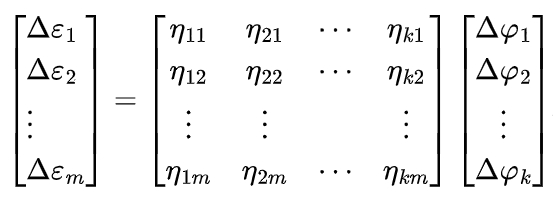
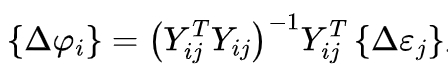
where Δε is the deviation at the i-th grid node, nij is the sensitivity coefficient of the i-th machining parameter at the j-th node, and Δφ is the correction amount of the i-th machining parameter. The sensitivity coefficient nij can be obtained by analyzing the sensitivity of the tooth surface deviation to the machining parameters. When m ≠ k, the machining parameters can be solved using:
3. Hypoid Gear Drive Axle Model
3.1 Model Building
A drive axle model is constructed to analyze the performance of hypoid gears, including transfer error and tooth root stress. The shaft system of the drive axle model is built using the dynamics software MASTA, and the axle housing model is meshed using the Hypermesh finite element analysis software and then assembled in MASTA. The axle housing is modeled with second – order tetrahedral elements, and unnecessary structures such as chamfers and bosses are removed as they have a minor impact on the gear dynamics analysis. The materials used for the axle housing, shaft system, and gears are structural steel, high – strength structural alloy steel, and carburized hardened steel, respectively. The completed drive axle model is shown in Figure 3.
The parameters of the drive axle model are presented. The hypoid gear model used in the drive axle follows the Gleason system and is made of carburized hardened steel. The gear parameters are Ymn detailed.
3.2 Acquisition of Sensitivity Coefficient Matrix
The hypoid gear is modified using the Specified Ease Off Surface function in MASTA’s Bevel Gear Manufacturing module. This function includes three major modification modules (Bias, Lead Relief, Profile Relief) with a total of 35 machining parameters. MASTA can automatically generate the Ease off graph and output the corresponding grid data. The Ease off graph of the unmodified pinion gear concave surface. By exporting the original tooth surface data and performing sensitivity analysis on the 35 machining parameters using the tooth shape modification data at 880 grid nodes, the sensitivity coefficient matrix is obtained.
4. Hypoid Gear Multi – objective Optimization
4.1 Transfer Error and Tooth Root Stress Calculation
The transfer error and tooth root stress of the modified hypoid gear are calculated using the Loading Tooth Surface Contact Analysis (LTCA) function in MASTA. LTCA is based on the gear finite element model and Hertz contact equation to calculate load distribution, tooth root stress, and transfer error. The finite element models of the hypoid gears are set up with specific parameters for the active and passive gears. The LTCA analysis is performed by setting the input load range and power flow, and the results include the peak – to – peak transfer error of the active gear and the maximum tooth root von Mises stress.
The relationship between the transfer error peak – to – peak values of the active and passive gears is proportional to the transmission ratio. The maximum tooth root stress of the active gear and the passive gear shows a similar trend. Therefore, reducing the transfer error and tooth root stress of the active gear can improve the overall performance of the gear set. The transfer error and tooth root stress results under different input loads are presented.
4.2 Meshing Power Loss Calculation
The meshing power loss Pmi of the hypoid gear is calculated using the formula:
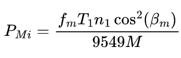
where fm is the meshing friction coefficient, T1 is the pinion torque, n1 is the pinion speed, βm is the midpoint spiral angle, and M is the meshing mechanical advantage. The meshing friction coefficient fm is calculated using Equation (9), and the meshing mechanical advantage M is calculated using Equation (10). The relevant parameters for calculating the meshing power loss are listed.
4.3 Surrogate Model Building
A BP artificial neural network surrogate model is established to describe the relationships between the five Ease off modification parameters and the performance parameters (transfer error, tooth root stress, and meshing power loss). The modification parameters are used as the input layer, and the performance parameters are used as the output layer. The neural network has a four – layer structure with 5×7×4×3 neurons. The training data for the surrogate model is selected based on the sensitivity analysis of the transfer error to the modification parameters. The thickness values of the model are chosen according to the sensitivity ranking, with more interpolation for parameters with higher sensitivity. A total of 240 sets of data are obtained and used to train the surrogate model. The output set of the surrogate model includes the average transfer error in the load range of 1000 – 5000 N·m, the maximum tooth root stress of the active gear in the same load range, and the meshing power loss at a load of 1000 N·m and an input speed of 1000 r/min. The surrogate model is validated using a verification set, and the results show that the model error is small, indicating the correctness of the model.
4.4 Hypoid Gear Multi – objective Optimization using NSGA – Ⅱ
The NSGA – Ⅱ algorithm is employed to optimize the hypoid gear. NSGA – Ⅱ is an improved multi – objective optimization algorithm with an elite strategy. The optimization variables are the five control coefficients of the Ease off function, with specific value ranges. The optimization objective functions are the average peak – to – peak transfer error of the active gear in the load range of 1000 – 5000 N·m, the average maximum tooth root stress of the active gear in the same load range, and the meshing power loss at a load of 1000 N·m and an input speed of 1000 r/min. All objective functions are minimized.
The population size is set to 100, and the maximum number of iterations is set to 1000. The optimization results. The optimal solution is selected based on specific criteria, and the verification results show that the surrogate model and MASTA dynamics calculations are in good agreement, confirming the correctness of the optimization results. The Ease off surface corresponding to the minimum transfer error solution is selected as the optimal surface. The transfer error and tooth root stress results of the optimal surface are presented.
The performance comparison before and after optimization demonstrates that the multi – objective optimization using Ease off effectively reduces the transfer error, tooth root stress, and meshing power loss of the hypoid gear.
5. Conclusion
5.1 Validation of the Proposed Method
Based on the Ease off topological modification theory, a hypoid gear drive axle model is established, and the machining parameters corresponding to the second – order Taylor expansion of the tooth surface deviation are derived using the sensitivity coefficient matrix. The modified gear model is built, and the correctness of the method is verified by comparing the errors between the Ease off tooth surface and the machined tooth surface.
5.2 Effectiveness of the Optimization Approach
By adjusting the Ease off modification parameters, the corresponding modified gear models are established. The transfer error peak – to – peak value, tooth root stress, and meshing power loss of the modified gears are calculated using MASTA software, and a neural network surrogate model is constructed. The NSGA – Ⅱ algorithm is used to optimize the surrogate model, and the results are verified by MASTA dynamics software. The results indicate that this method can effectively reduce the transfer error, tooth root stress, and meshing power loss of hypoid gears, providing a valuable approach for hypoid gear design and optimization.
Future research can focus on further improving the optimization algorithm, exploring more performance parameters, and applying the proposed method to different types of hypoid gear systems. Additionally, experimental validation of the optimized gears can enhance the practical significance of the research.