
3D modeling of the helical gear pair corresponding to the optimal solution B before and after optimization using MASTA software. Apply a torque of 286.47N · m to the pinion gear of the driving wheel and release the freedom of the pinion gear to rotate around the Z-axis, fix the wheel gear, set 5 nodes along the tooth height direction for the wheel and pinion gears, and set 9 nodes along the tooth width direction to obtain the tooth surface mesh of the wheel and pinion gears, as shown in Figure 1. After completing the 3D modeling, perform static simulation.
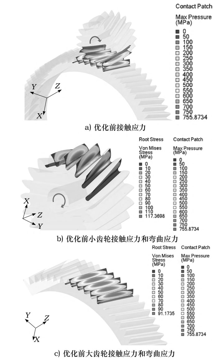
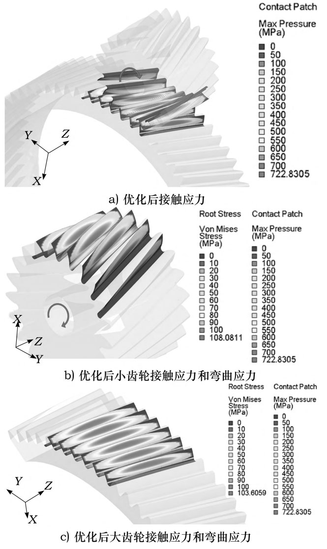
Contact simulation was conducted on the helical gear pair using MASTA software to obtain the contact stress and bending stress cloud maps of the wheel and pinion gears under working conditions before and after optimization, as shown in Figure 2 and Figure 3, respectively. The arrows in Figures 2a), 2b), 3a), and 3b) indicate the direction of torque application. From Figures 4a) and 3a), it can be seen that the maximum contact stresses of the helical gear pair before and after simulation optimization are 755.8734 and 722.8305MPa, respectively. The errors between the theoretical calculation of the maximum contact stresses before and after optimization are 4.85% and 5.18%, respectively. From Figures 2b) and 2c), it can be seen that the maximum bending stresses at the roots of the wheel and pinion gears before simulation optimization are 91.1735 MPa and 117.3698 MPa, respectively. The difference in bending stresses is 26.1963 MPa, which is 4.8386 MPa higher than the difference in maximum bending stresses at the roots of the wheel and pinion gears before theoretical calculation optimization. From Figure 3b) and Figure 3c), it can be seen that the maximum bending stresses at the tooth roots of the optimized wheel and pinion gears are 103.6059 and 108.0811 MPa, respectively. The difference in bending stresses is 4.4752 MPa, which is 1.7359 MPa higher than the difference in maximum bending stresses at the tooth roots of the theoretically optimized wheel and pinion gears. From this, it can be seen that there are some differences between the simulation results and the theoretical calculation results, but they meet the engineering accuracy requirements and verify the correctness of the theoretical calculation results.