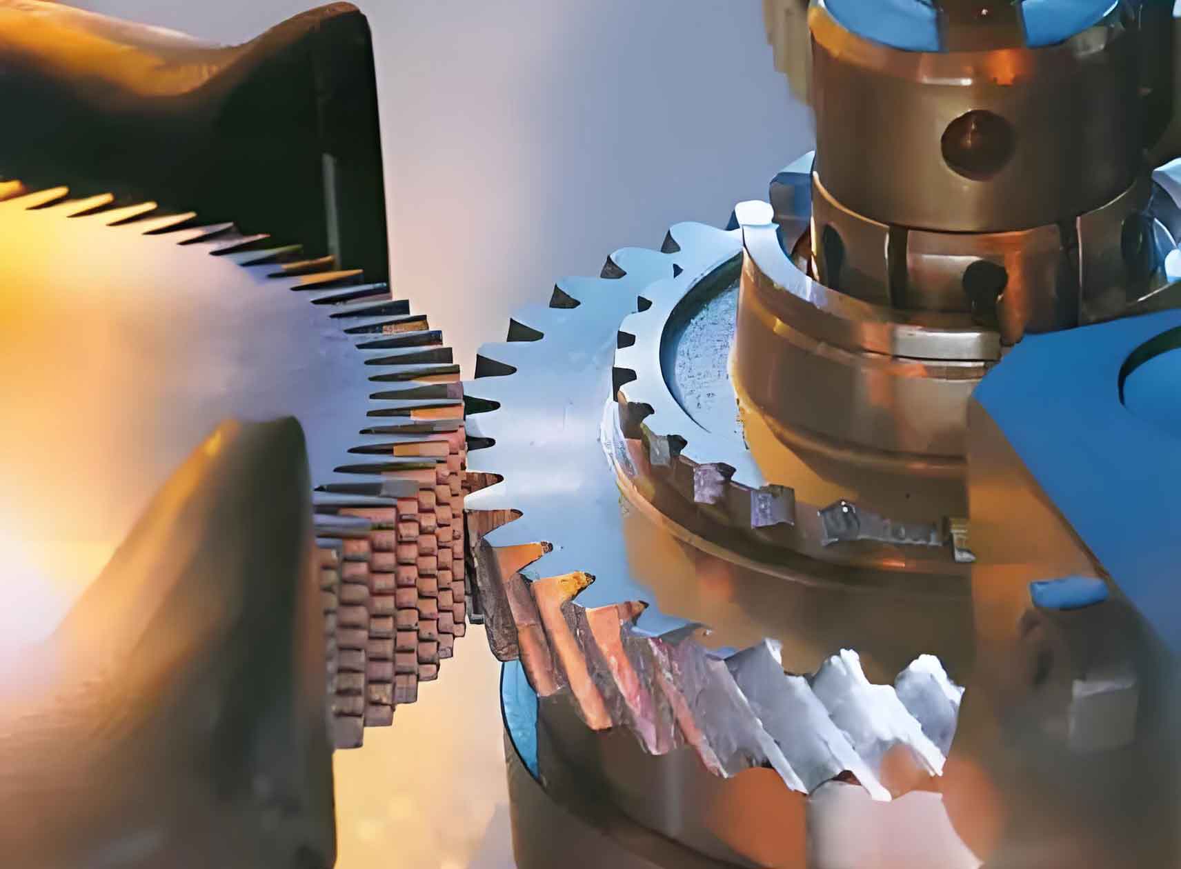
Tooth profile concave error during gear shaving remains a critical challenge in gear manufacturing, causing vibration, noise, and reduced service life. We develop a multi-source coupled prediction model that integrates installation errors, kinematics, and contact dynamics to quantify this phenomenon. Unlike single-factor approaches, our model couples key parameters through the novel concept of mesh point single cutting area, enabling accurate error prediction and mechanistic analysis.
Integrated Gear Shaving Analysis Model
Our model incorporates four installation errors: axial angle error (ΔΣ), center distance error (Δa), and high-speed axis synchronization errors (Δω₁, Δω₂). The relative sliding velocity at the meshing point is derived as:
$$ \begin{cases} V_x = -\omega’_2 z \sin\Sigma’ + \omega’_2 y \cos\Sigma’ – \omega’_1 y \\ V_y = \omega’_1 x – \omega’_2 (x – a’) \cos\Sigma’ – v_{02} \sin\Sigma’ \\ V_z = \omega’_2 (x – a’) \sin\Sigma’ – v_{02} \cos\Sigma’ \end{cases} $$
where Σ’ = Σ + ΔΣ, a’ = a + Δa, ω’₁ = ω₁ + Δω₁, and ω’₂ = ω₂ + Δω₂. The actual cutting velocity component perpendicular to the cutting edge is:
$$ V_1 = \omega_2 (x – a’) \sin\Sigma’ \cos\beta_2 + \omega_2 (x – a’) \cos\Sigma’ \sin\beta_1 + v_{02} \sin\Sigma’ \sin\beta_1 – v_{02} \cos\Sigma’ \cos\beta_2 – \omega_1 x \sin\beta_1 $$
Installation errors shift the meshing trajectory, altering the induced normal curvature:
$$ K = \frac{\sin\lambda – \left[1 – \frac{1}{r_{b1}} + P^2 r_{b1} \sin\Sigma’ \cos\Delta_1 + P \cos\Sigma’ \right]}{\sqrt{x^2 + y^2 + z^2}} $$
with Δ₁ = arctan(x/y) – arcsin[r_{b1}(x² + y²)^{-1/2}]. Back-cutting depth (a_p) combines radial feed, elastic compression, and tooth bending:
$$ a_p = \frac{\Delta}{2 \sin\alpha} + e \left( \frac{3\pi\lambda F_{nc}}{2 \sum_{i=1}^m K c_i^{3/2}} \right)^{2/3} + \sum_{i=1}^n (\delta_{FAAvi} – \delta_{FBAvi}) + \sqrt{(z \sin\Sigma’ – y \cos\Sigma’)^2 + (x + a’)^2} \sin\Sigma’ $$

Single Cutting Area Coupling Mechanism
We introduce the mesh point single cutting area (U) to couple multi-source factors. This metric integrates contact ratio, kinematics, and installation errors by calculating the material removed per tool-workpiece engagement cycle:
$$ U = \int_{\phi_1}^{\phi_3} a’_p (\phi) V_1 (\phi) d\phi $$
where φ₁, φ₂, φ₃ represent start, maximum depth, and end contact states. The actual depth of cut (a’_p) varies with tool rotation angle (φ):
$$ a’_p(\phi) = \begin{cases} a_p(\phi) – \int_{s(\phi)}^{s(\phi_2)} K(\phi) ds & \phi_1 < \phi < \phi_2 \\ a_p(\phi) – \int_{s(\phi_2)}^{s(\phi)} K(\phi) ds & \phi_2 < \phi < \phi_3 \end{cases} $$
Cutting length (l) is derived from velocity integration: \( l = \int V_1(\phi) d\phi \). This coupling reveals that excessive U directly correlates with concave error formation.
GA-BP Neural Network Prediction Model
We establish a prediction model using Genetic Algorithm-optimized Backpropagation Neural Networks (GA-BP). The network architecture takes Umax, Umin, and position θmax as inputs, outputting concave error magnitude (E) and location (θ). The fitness function minimizes prediction error:
$$ f(x) = \frac{1}{\sum (T – O)^2 / N} $$
where T and O are target and predicted values, and N is sample count. Key network parameters include:
| Parameter | Value |
|---|---|
| Hidden Layers | 1 |
| Neurons per Layer | 10 |
| Training Epochs | 10,000 |
| Learning Rate | 0.01 |
| Target MSE | 0.0001 |
Validation and Parametric Analysis
Experimental validation used four shaving cutters with varying contact ratios (1.6548–1.8294). The GA-BP model achieved 6.93% mean error in E and 2.19% in θ location:
| Umax (μm²) | Umin (μm²) | E Predicted (mm) | E Actual (mm) | Error (%) |
|---|---|---|---|---|
| 2.157 | 0.745 | 0.0303 | 0.0321 | 5.56 |
| 2.349 | 0.846 | 0.0249 | 0.0267 | 6.48 |
| 1.216 | 0.397 | 0.0213 | 0.0229 | 6.95 |
| 0.804 | 0.216 | 0.0181 | 0.0194 | 6.46 |
Concave error increases with U until a critical threshold, beyond which plastic deformation causes self-correction. The error location shifts toward the tooth tip with increasing U due to asymmetric bending stiffness:
$$ \delta_w = \delta_{FAAw} – \delta_{FBAw} $$
Parametric studies reveal complex relationships between cutting parameters and Umax:
| Parameter | Change | ΔUmax | Mechanism |
|---|---|---|---|
| Contact Ratio | 1.6548→1.8294 | +0.94 μm² | Increased cutting length dominates curvature reduction |
| Radial Feed | 3.3→5.8 μm/s | +167% | Direct increase in depth of cut |
| Spindle Speed | 6→12 r/s | -38.2% | Reduced contact duration per cycle |
| ΔΣ | 0.1°→0.7° | +61.4% | Altered contact geometry and depth |
| Δa | 0.01→0.06 mm | +26.3% | Increased effective depth of cut |
Conclusions
Our multi-source coupled model demonstrates that mesh point single cutting area serves as an effective coupling parameter for gear shaving error prediction. Key findings include:
- Excessive single cutting area (>1.8 μm²) is the primary cause of concave errors in gear shaving processes.
- The GA-BP prediction model achieves <6.93% error by incorporating Umax, Umin, and θmax.
- Concave error location migrates toward the tooth tip as U increases due to differential bending stiffness.
- Optimal gear shaving requires balancing contact ratio (1.7–1.8), minimizing radial feed (<4 μm/s), and controlling axial angle error (<0.3°).
This approach enables quantitative prediction of gear shaving errors under real-world installation inaccuracies, providing a foundation for adaptive compensation strategies in precision gear manufacturing.
