
In this thesis, I systematically investigate the multi-state meshing-impacting nonlinear dynamic characteristics of spur gears under gear tooth breakage conditions. The research is motivated by the fact that spur gears are widely used in aerospace, automotive, and marine applications where tooth fractures can occur during prolonged service. In particular, I focus on two typical failure modes: local tooth chipping and tooth root breakage. Both defects alter the instantaneous contact state, reduce the local meshing stiffness, and may induce undesired back-side impact phenomena. To capture these effects, I establish a refined physical model of a spur gear pair that incorporates time-varying contact characteristics, energy dissipation during tooth back collision, and multi-state motion switching. I then derive dimensionless equations of motion for a standard involute spur gear system and a high-contact-ratio spur gear system, respectively. Using numerical integration together with Poincaré mapping, bifurcation diagrams, contact force charts, phase portraits, and frequency spectra, I reveal the complex evolution of meshing, disengagement, and back-side collision as key system parameters vary. Finally, I perform finite element simulations to evaluate the equivalent stress distribution under tooth breakage conditions. The results provide theoretical guidance for fault prognosis and parameter optimization of spur gear drives.
1. Introduction
Spur gears are fundamental components in mechanical transmission systems. Their dynamic performance directly affects the reliability, noise level, and service life of the entire machine. With the increasing demand for high-speed, high-precision, and high-power-density gear drives, the nonlinear dynamics of spur gears has attracted considerable attention. The main sources of nonlinearity include time-varying meshing stiffness, time-varying backlash, friction, transmission errors, and multi-state contact behavior. Among these, the loss of tooth contact and the subsequent back-side impact are particularly dangerous since they cause severe vibration and may lead to unexpected failure.
Tooth breakage is one of the most severe failure modes of spur gears. It may occur due to excessive overload, fatigue crack propagation, or accidental impact. Local tooth chipping often begins at the tooth tip or edge, while root breakage usually initiates from stress concentration at the fillet. When a tooth breaks away, the adjacent teeth immediately experience a higher load, and the overall meshing stiffness is reduced locally. Furthermore, the broken tooth may cause the gear pair to temporarily lose contact, and if the driving tooth hits the driven tooth on the back side, a high-magnitude impulsive force is generated. This phenomenon is known as back-side collision or tooth impact. Traditional models often idealize the back-side contact as a continuous meshing process, which is not physically accurate because the back-side contact occurs in a very short time interval and involves instantaneous velocity changes. To overcome this limitation, I introduce a continuous contact-impact force model with a restitution coefficient to describe the energy dissipation during the back-side collision. In this way, the spur gear system is modeled as a hybrid dynamic system that switches among several distinct states: regular face meshing, disengagement, and back-side collision.
The main contributions of this work are summarized as follows. First, I develop a multi-state meshing-impacting model for spur gears that explicitly incorporates tooth breakage. Second, I derive explicit formulas for time-varying meshing stiffness and load-sharing ratio considering the broken tooth effects. Third, I analyze the bifurcation and chaos characteristics of the damaged spur gear system under varying load and frequency conditions. Finally, I compare the results with the healthy spur gear system and validate the stress concentration phenomenon using finite element method.
2. Physical Model of Spur Gear Pair with Meshing-Impact
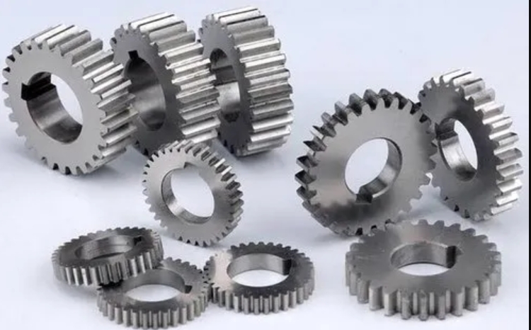
Figure 1 shows the simplified physical model of a spur gear pair that I use as the basis for the dynamic analysis. The model consists of a driving gear and a driven gear with base circle radii \(R_{bp}\) and \(R_{bg}\), respectively. The torsional displacements are denoted by \(\theta_p\) and \(\theta_g\). The external torques are \(T_p\) and \(T_g\). The gear pair is subjected to a time-varying meshing stiffness \(k_m(\tau)\) and a constant meshing damping \(c_g\). The gear backlash half-gap is \(D\). The dynamic transmission error includes a time-varying component \(e(\tau)=E_a \cos(\omega_h \tau)\), where \(E_a\) is the error amplitude and \(\omega_h\) is the meshing frequency. The contact force model for the back-side impact uses a restitution coefficient \(R\).
Let the relative displacement along the line of action be defined as
\[
x = R_{bp}\theta_p – R_{bg}\theta_g – e(\tau).
\]
Based on the value of \(x\) with respect to the backlash boundaries, the spur gear pair can be in one of the following states:
- Face meshing: \(x \ge D\). The teeth are in contact on the driving side.
- Disengagement: \(-D < x < D\). The teeth are separated and there is no contact force.
- Back-side collision: \(x = -D\). The teeth collide on the back side. This is treated as an instantaneous impact with a coefficient of restitution \(0<r<1\).
- </r<1\).
For the local chipping fault, the broken tooth leaves the mesh earlier than a healthy tooth, so the effective contact ratio is reduced. For the tooth root breakage, the affected tooth pair loses its contact completely, and the number of simultaneously meshing teeth decreases. In both cases, the state switching instants depend on the location of the broken tooth in the rotation cycle.
3. Time-Varying Meshing Stiffness and Load Sharing
3.1 Contact Stiffness Model
The total meshing stiffness is composed of several parts: Hertzian contact stiffness \(k_h\), bending stiffness \(k_{bji}\), axial compression stiffness \(k_{aji}\), shear stiffness \(k_{sji}\), and fillet-foundation stiffness \(k_{fji}\). For the high-contact-ratio spur gear system, I also include the thermal stiffness \(k_{tji}\). The subscripts \(j=p,g\) denote the driving and driven gears, and \(i=1,2,3\) denote the number of tooth pairs in contact. The total mesh stiffness is written as
\[
\frac{1}{k_m(\tau)} = \frac{1}{k_h} + \sum_{j=p,g}\sum_i \left( \frac{1}{k_{bji}} + \frac{1}{k_{aji}} + \frac{1}{k_{sji}} + \frac{1}{k_{fji}} + \frac{1}{k_{tji}} \right).
\]
The Hertzian contact stiffness is given by
\[
k_h = \frac{1}{\frac{1}{h_1}+\frac{1}{h_2}}\frac{4}{3}\sqrt{\frac{r_1 r_2}{r_1+r_2}},
\]
where \(r_1\) and \(r_2\) are the equivalent curvature radii at the contact point, and \(h_i = (1-\nu_i^2)/(\pi E_i)\) for \(i=1,2\). The bending stiffness is calculated by integrating along the tooth profile:
\[
\frac{1}{k_{bji}} = \int_{-\alpha_1}^{\alpha_2} \frac{3\cos^2\alpha_{ji}\left[1+\cos\alpha_{ji}(\tan\alpha_{ji}-\tan\alpha)\right]^2}{2E B \left(\sin\alpha+\cos\alpha\right)^2} \,\mathrm{d}\alpha,
\]
where \(E\) is the Young’s modulus, \(B\) is the face width, and \(\alpha\) is the angle parameter.
3.2 Effect of Local Chipping on Meshing Stiffness
For the local chipping fault, the broken tooth tip moves the effective end of the line of action from point \(D\) to point \(D_1\). As a result, the total contact ratio decreases from \(\varepsilon_m\) to \(\varepsilon_b\). The double-tooth contact zone becomes smaller and the single-tooth contact zone becomes larger. I define the following state functions for the damaged cycle:
\[
h_{bs}(\tau,x) = \begin{cases}
\lambda_{d1}\mu_{d1}g_{d1}(\tau)L_1(\tau) + c_g \dot{x} + k_m(\tau)(x-D), & x\ge D,\\
0, & -D<x<d,
and for the double-tooth contact case,
\[
h_{bd}(\tau,x) = \begin{cases}
\sum_{i=1}^2 \lambda_{di}\mu_{di}g_{di}(\tau)L_i(\tau) + c_g \dot{x} + k_m(\tau)(x-D), & x\ge D,\\
0, & -D<x<d.
The stiffness in the damaged single/double contact regions is lower than that of the healthy gear pair, which leads to a higher load on the adjacent teeth.
3.3 Effect of Tooth Root Breakage on Meshing Stiffness
Tooth root breakage changes the continuous meshing condition. For a high-contact-ratio spur gear, the healthy gear pair has alternating three-tooth and two-tooth contact zones. When one tooth is broken at the root, the three-tooth contact becomes two-tooth contact, and the two-tooth contact becomes single-tooth contact. Consequently, the contact ratio remains greater than 1, but the number of sharing teeth is reduced. The time-varying meshing stiffness \(k_m(\tau)\) is significantly reduced in the affected interval. The corresponding load-sharing ratio \(L_i(\tau)\) is calculated from the ratio of individual tooth stiffness to the total stiffness:
\[
L_i(\tau) = \frac{k_i(\tau)}{\sum_{i=1}^{n} k_i(\tau)},
\]
where \(n=2\) for the damaged three-tooth contact and \(n=1\) for the damaged two-tooth contact.
To summarize the expected variation, I compare the stiffness and load-sharing behavior in the table below.
| Fault type | Contact ratio | Contact state | Mesh stiffness | Load sharing |
|---|---|---|---|---|
| Healthy gear | \(\varepsilon_m\) | Multi-pair contact | Nominal stiffness | Balanced load distribution |
| Local chipping | \(\varepsilon_b<\varepsilon_m\) | Reduced double-tooth zone | Local stiffness drop | High load on adjacent teeth |
| Root breakage | Still \(>1\) | Three-tooth \(\to\) two-tooth, two-tooth \(\to\) single-tooth | Stiffness drops at broken interval | Load concentration near the broken tooth |
4. Multi-State Meshing-Impact Dynamic Model
4.1 Equations of Motion for Local Chipping Fault
I apply Newton’s second law to the torsional motion of the spur gear pair. For the double-tooth engagement state, the equation is
\[
I_p\ddot{\theta}_p = T_p – R_{bp}\left(F_{Np1}+F_{fp1}\right) – R_{bp}\left(F_{Np2}+F_{fp2}\right),
\]
\[
I_g\ddot{\theta}_g = -T_g + R_{bg}\left(F_{Ng1}+F_{fg1}\right) + R_{bg}\left(F_{Ng2}+F_{fg2}\right).
\]
In the above, \(F_{Npi}\) and \(F_{Ngi}\) are the normal contact forces, while \(F_{fpi}\) and \(F_{fgi}\) are the friction forces. The normal contact force on the \(i\)-th tooth pair is \(F_{Ni}=L_i(\tau)F_m\), with \(F_m=k_m(\tau)(x-D)+c_g\dot{x}\). The friction force includes the friction coefficient \(\mu_{di}\) and the direction coefficient \(\lambda_{di}\). Substituting these into the equations and reducing to the relative coordinate \(x\) gives
\[
m_e \ddot{x} + \sum_{i=1}^2 \lambda_{di}\mu_{di}g_{di}(\tau)L_i(\tau) + c_g\dot{x} + k_m(\tau)(x-D) = F + F_h(\tau),
\]
where \(m_e\) is the equivalent mass, \(F\) is the external load parameter, and \(F_h(\tau)=-m_e\ddot{e}(\tau)\) is the internal excitation.
For the single-tooth engagement I and II, the equation is simplified to
\[
m_e \ddot{x} + \lambda_{d1}\mu_{d1}g_{d1}(\tau)L_1(\tau) + c_g\dot{x} + k_{ms}(\tau)(x-D) = F + F_h(\tau).
\]
When the gear pair is disengaged, the relative motion is governed by
\[
m_e \ddot{x} = F + F_h(\tau).
\]
For the back-side collision, I use the continuous impact force model. Let \(x=-D\) be the contact point. The impact formulation is
\[
\dot{x}^+ = -R\,\dot{x}^-,
\]
where \(\dot{x}^-\) and \(\dot{x}^+\) are the relative velocities before and after impact, respectively. The impact force is represented by the maximum deformation contact force
\[
F_c = \frac{2}{5}\frac{k_c(\tau)}{\left[k_c(\tau)\right]^{2/5}}\left(\frac{5}{4}m_e(1-R^2)(\dot{x}^-)^2\right)^{2/5}.
\]
This formulation captures the instantaneous energy dissipation during the back-side impact.
4.2 Equations of Motion for Root Breakage in High-Contact-Ratio Spur Gears
For a high-contact-ratio spur gear, the healthy state has alternating three-tooth and two-tooth contacts. I denote the three-tooth contact state by
\[
m_e \ddot{x} + \sum_{i=1}^3 \lambda_{di}\mu_{di}g_{di}(\tau)L_i(\tau) + c_g\dot{x} + k_{mt}(\tau)(x-D) = F + F_h(\tau).
\]
When the root-broken tooth enters the mesh, the three-tooth contact degenerates into a two-tooth contact. I denote this state as “double-tooth engagement II”. Its equation is
\[
m_e \ddot{x} + \sum_{i=1}^2 \lambda_{di}\mu_{di}g_{di}(\tau)L_i^*(\tau) + c_g\dot{x} + k_{md}^*(\tau)(x-D) = F + F_h(\tau).
\]
Similarly, the two-tooth contact degenerates into single-tooth engagement, written as
\[
m_e \ddot{x} + \lambda_{d1}\mu_{d1}g_{d1}(\tau)L_1^*(\tau) + c_g\dot{x} + k_{ms}^*(\tau)(x-D) = F + F_h(\tau).
\]
The state function \(h(\tau,x)\) selects the appropriate equation based on the tooth pair number and the damaged interval. The complete multi-state model can be expressed as
\[
m_e \ddot{x} – h(\tau,x)\,f(x,\dot{x}) = F + F_h(\tau),
\]
where
\[
f(x,\dot{x}) = \begin{cases}
k_m(\tau)(x-D)+c_g\dot{x}, & x\ge D,\\
0, & -D<x<d,
and \(h(\tau,x)\) depends on the specific contact configuration and the damaged tooth position.
4.3 Dimensionless Formulation
Let the characteristic length be \(D_c\) and the natural frequency be \(\omega_n = \sqrt{k_{av}/m_e}\), where \(k_{av}\) is the average mesh stiffness. Define the normalized time \(t=\omega_n \tau\), normalized displacement \(x_n = x/D_c\), normalized backlash \(D_n = D/D_c\), normalized damping \(c_n = c_g/(m_e\omega_n)\), normalized load \(F_n = F/(m_e D_c \omega_n^2)\), normalized stiffness \(k_n(t) = k_m(\tau)/(m_e\omega_n^2)\), and normalized excitation \(F_{hn}(t) = \cos(\omega t)\), where \(\omega = \omega_h/\omega_n\) is the frequency ratio. The dimensionless equation is
\[
\ddot{x}_n – h_n(t,x_n)\,f_n(x_n,\dot{x}_n) = F_n + \varepsilon \omega^2 \cos(\omega t),
\]
where \(\varepsilon\) is the dimensionless error coefficient. The impact condition becomes \(x_n=-D_n\). The dimensionless impact force is obtained from the same model.
Table 3 lists the key dimensionless parameters used in the numerical analysis.
| Parameter | Symbol | Definition |
|---|---|---|
| Dimensionless displacement | \(x_n\) | \(x/D_c\) |
| Dimensionless backlash | \(D_n\) | \(D/D_c\) |
| Dimensionless damping | \(c_n\) | \(c_g/(m_e\omega_n)\) |
| Dimensionless load | \(F_n\) | \(F/(m_eD_c\omega_n^2)\) |
| Dimensionless stiffness | \(k_n(t)\) | \(k_m(\tau)/(m_e\omega_n^2)\) |
| Frequency ratio | \(\omega\) | \(\omega_h/\omega_n\) |
| Error coefficient | \(\varepsilon\) | \(E_a/D_c\) |
5. Numerical Analysis of Local Chipping Fault
I employ the fourth-order variable-step Runge-Kutta method to solve the dimensionless equations. I define three Poincaré sections: a stroboscopic section \(\beta_t = \{(x,\dot{x},t)\,|\,t \bmod (2\pi/\omega)=0\}\), a tooth-face impact section \(\beta_d = \{(x,\dot{x},t)\,|\,x=D\}\), and a back-side impact section \(\beta_b = \{(x,\dot{x},t)\,|\,x=-D\}\). These sections help to identify the type of motion and the occurrence of impact events.
5.1 Contact Force Evolution
I first fix the system parameters as \(D=1\), \(c_n=0.01\), \(\varepsilon=0.05\), \(F_n=0.05\), \(\mu_{d1}=\mu_{d2}=0.15\), \(\omega=1.1\), and \(R=0.85\). The time history of the dimensionless contact force \(F_m\) is shown in Figure 2. The force alternates between positive (face meshing), zero (disengagement), and negative (back-side collision) values. The presence of the broken tooth reduces the local contact force and increases the duration of the single-tooth contact zone. This phenomenon is much more pronounced when the broken tooth enters the meshing region.
5.2 Influence of Load Coefficient
I then vary the dimensionless load coefficient \(F_n\) in the interval \((0,0.15]\) with \(\omega=1.2\). The bifurcation diagram with two initial conditions is depicted in Figure 3. For large \(F_n\), the system exhibits a stable period-1 motion without back-side collision. As \(F_n\) decreases, the period-1 motion bifurcates into a period-4 motion and simultaneously a period-2 attractor appears. Thus, multi-attractor coexistence occurs. The existence of multiple attractors makes the response sensitive to initial conditions. When \(F_n\) is further decreased, the system enters chaotic motion and the back-side collision force appears. The positive peak of the contact force becomes irregular. This indicates that low load conditions tend to induce tooth separation and subsequent impact.
I summarize the observed dynamic behavior for different load levels in Table 4.
| Load range | Motion type | Back-side collision | Coexisting attractors |
|---|---|---|---|
| \(F_n > 0.09\) | Period-1 | No | Single |
| \(0.05 < F_n < 0.09\) | Period-2 and period-4 | Appears for lower \(F_n\) | Two coexisting attractors |
| \(0.03 < F_n < 0.05\) | Chaos and period-4 | Yes | Multiple |
| \(F_n < 0.03\) | Period-6, period-3 | Yes | Sometimes two |
5.3 Influence of Meshing Frequency
Next, I fix \(F_n=0.11\) and vary the frequency ratio \(\omega\) from 0.1 to 2.5. The bifurcation diagram is shown in Figure 4. At low frequencies, the system is chaotic and the back-side collision force is large. As \(\omega\) increases, the chaotic motion converts to period-1 motion, and the back-side collision disappears. At intermediate frequencies, period-2 and period-3 motions coexist, leading to beating phenomena. At high frequencies, the system again becomes chaotic and back-side collisions reappear. These results show that an inappropriate frequency range may cause severe impact and noise. Therefore, in practical spur gear design, one should avoid low and high frequency ranges near the resonance and chaotic regions.
5.4 Comparison with Healthy Spur Gear System
I compare the bifurcation diagram of the damaged system with that of the healthy system under the same load parameter. The healthy system shows a simpler bifurcation scenario for large loads: it remains period-1 with no impact. The local chipping fault introduces earlier bifurcations and more coexisting attractors. This indicates that the tooth breakage significantly increases the dynamic complexity of spur gears, especially under moderate loads.
6. Numerical Analysis of Tooth Root Breakage
6.1 Contact Force Response
For the high-contact-ratio spur gear with a root-broken tooth, I use the parameters listed in Table 5. The healthy gear pair has a contact ratio above 2, while the broken gear pair still has a contact ratio above 1. I study three typical motion patterns: pure face meshing, face meshing–disengagement alternation, and face meshing–disengagement–back-side collision alternation.
| Gear parameter | Pinion | Gear |
|---|---|---|
| Number of teeth | 40 | 55 |
| Module \(m\) (mm) | 3 | 3 |
| Addendum coefficient | 1.2 | 1.2 |
| Clearance coefficient | 0.25 | 0.25 |
| Pressure angle \(\alpha_0\) (°) | 20 | 20 |
| Face width \(B\) (mm) | 40 | 40 |
| Young’s modulus \(E\) (N/mm²) | 206 | 206 |
| Moment of inertia \(I\) (kg·m²) | \(5.25\times10^{-3}\) | \(17.83\times10^{-3}\) |
| Poisson’s ratio | 0.3 | 0.3 |
When the system is purely in face meshing, the broken tooth causes a local reduction of the contact force, while the adjacent teeth experience a larger force. The force time history becomes near-periodic with a period that is three times the meshing period. The phase portrait of the damaged system has a larger topological structure than that of the healthy system, indicating stronger vibration.
When the system alternates between face meshing and disengagement, the broken tooth may cause the gear pair to enter the disengagement state earlier. The disengagement ratio, defined as the fraction of time during which \(F_m=0\), changes accordingly. I compute the disengagement ratio for different backlash and load values. The results are shown in Table 6.
| Varied parameter | Value | Disengagement ratio | Back-side collision force |
|---|---|---|---|
| Backlash \(D\) | 0.5 | 0.42 | 0.58 |
| 1.0 | 0.55 | 0.81 | |
| 1.5 | 0.68 | 1.15 | |
| Load \(F\) | 0.04 | 0.64 | 0.76 |
| 0.12 | 0.71 | 0.78 | |
| 0.20 | 0.79 | 0.79 |
It is worth noting that increasing the backlash leads to a larger impact force and a larger disengagement ratio. Increasing the load also increases the disengagement ratio, but the back-side collision force is only mildly affected.
6.2 Bifurcation with Respect to Frequency Ratio
I fix \(F_n=0.05\), \(\varepsilon=0.08\), and vary \(\omega\) from 0.4 to 4.0. The bifurcation diagram in Figure 5 shows a rich variety of periodic and chaotic motions. For \(\omega\ge 3.0\), the system settles to a stable period-1 motion with no back-side collision. As \(\omega\) decreases, the motion is replaced by a chaotic attractor and then by period-3 motion. A period-doubling cascade leads to period-6 motion before the system enters chaos again. The back-side collision appears only in the chaotic and high-order periodic regions. This confirms that chaos is a main cause of back-side impact.
6.3 Bifurcation with Respect to Error Coefficient
Next, I fix \(\omega=2.0\) and \(F_n=0.05\), and vary the error coefficient \(\varepsilon\) from 0 to 0.2. The resulting bifurcation diagram is shown in Figure 6. For very small \(\varepsilon\), the system is period-1 with pure face meshing. At \(\varepsilon\approx0.005\), a small disengagement zone appears. As \(\varepsilon\) increases, the system undergoes a series of period-2, period-3, period-6, period-12 motions and then enters chaos. The back-side collision occurs only when \(\varepsilon\) exceeds a threshold and the motion becomes chaotic or high-periodic. In the range \(0.03<\varepsilon<0.08\), the damaged system shows a period-3 to period-12 route via reverse period-doubling bifurcations, which is not observed in the healthy system. This reveals that the tooth root breakage dramatically changes the bifurcation topology of the spur gear pair.
6.4 Comparison between Healthy and Broken High-Contact-Ratio Spur Gears
I compare the bifurcation diagram of the healthy system with the damaged system under the same error coefficient range. The healthy system has a simpler route from period-1 to chaos, with a narrower period-3 window. The broken system introduces an additional period-12 bifurcation branch and multiple subcritical bifurcations. Therefore, the presence of a root-broken tooth can significantly increase the number of possible steady-state responses. This is important for condition monitoring because the appearance of new periodic windows may be used as a fault signature.
7. Finite Element Verification
To verify the stress concentration effect caused by tooth breakage, I build three-dimensional finite element models of the spur gear pair using the geometry parameters given in Table 1 and Table 5. I apply a nominal torque and use a friction coefficient of 0.15. The equivalent stress distributions are compared at the same meshing position for both healthy and damaged cases.
For the local chipping case, the healthy double-tooth contact has a maximum equivalent stress of 538 MPa. When the broken tooth turns the double-tooth contact into a single-tooth contact, the maximum equivalent stress increases to 1045 MPa. The stress concentration is observed at the tooth fillet and at the adjacent tooth pair. For the tooth root breakage case, the healthy three-tooth contact has a maximum stress of 396 MPa. When the broken tooth reduces the contact to two teeth, the stress increases to 495 MPa. When the two-tooth contact reduces to a single-tooth contact, the stress reaches 615 MPa.
These finite element results confirm that the reduction of load-sharing tooth pairs leads to a pronounced increase in contact stress. The higher stress can accelerate fatigue crack growth and may cause secondary failures in the adjacent teeth of spur gears.
8. Conclusion
In this thesis, I have investigated the multi-state meshing-impacting nonlinear dynamics of spur gears with two typical tooth breakage faults: local chipping and tooth root breakage. A comprehensive dynamic model was developed by considering time-varying meshing stiffness, load sharing, backlash, friction, and a dissipative contact-impact model for the back-side collision. The main conclusions are as follows:
- Tooth breakage reduces the local meshing stiffness and alters the contact ratio. The affected gear pair loses a load-sharing tooth pair, which causes a local force drop and a force increase on the adjacent teeth. This leads to stress concentration and reduces the fatigue life of the spur gear pair.
- The multi-state model, which includes face meshing, disengagement, and back-side collision, accurately captures the transient nature of the back-side impact. The dimensionless formulation provides a convenient framework for bifurcation and chaos analysis.
- For local chipping, the load coefficient and meshing frequency strongly influence the dynamic response. Low loads and extreme frequencies are more likely to induce chaotic motion and back-side collisions. Multi-attractor coexistence is found in a wide frequency range, which makes the response sensitive to initial conditions.
- For tooth root breakage in high-contact-ratio spur gears, the fault changes the sequence of tooth contacts and induces additional periodic windows. The error coefficient has a critical effect: small errors suppress back-side collisions, while large errors promote chaotic impact behavior.
- Finite element results confirm that the equivalent stress increases significantly when the number of simultaneously meshing teeth is reduced. The stress concentration occurs near the tooth root and on adjacent teeth. This provides a physical explanation for the vibration and noise induced by tooth breakage.
This work offers a new perspective on the modeling and analysis of damaged spur gears. The results can be used to predict impact risk, optimize gear parameters, and develop fault diagnosis strategies for practical gear transmission systems.
</x</x</x