
The non-circular gear transmission test bench is a horizontal mechanism, which is composed of precision mechanical system, measurement and control system, measurement software and other parts. The non-circular gear transmission test bench built is shown in Figure 1. This test bench can be used for various types of reducers. The reducer mounting bracket is fixed in the middle of the base. A linear guide rail is installed on the cast iron platform base. The movement of the input end assembly and the output end assembly is realized through the non-circular gear-rack mechanism (Fig. 1b). The detailed configuration information of the test bench is shown in the table.
| Part name | Model | Specifications |
| Torque sensor | YH-502 | The measuring ranges are 20N · m and 2000N · m respectively; The measurement accuracy is ± 0.1%; Power supply voltage: 24VDC; Output signal: 10 ± 5kHz; Torque accuracy:<± 0.1% F.S; Frequency response: 100 μ s |
| Noise sensor | RS-ZS-V05-2 | Range: 30-120dB; Frequency range: 20Hz-12.5kHz; Measurement error: ± 1.5dB Infrared temperature sensor CK-01A temperature range: – 20~300 ℃; Spectral range: 8-14 μ m; Measurement accuracy: ± 1%; Response time: 50-300MS optional; |
| Infrared temperature sensor | CK-01A | Temperature range: – 20~300 ℃; Spectral range: 8-14 μ m; Measurement accuracy: ± 1%; Response time: 50-300MS optional; |
| Vibration sensor | CA-YD-107 | Frequency response: 0.5-6000Hz; Maximum transverse sensitivity: ≤ 5%; Axial sensitivity 50PC/g; Magnetic sensitivity: 2g/T; Base strain: 0.2mg/ μ g |
| Circular grating | K-100 | Power supply voltage: 24VDC; Resolution: 48000P/R; Protection grade: IP50 |
| AC servo motor | MSME504G | Rated speed: 3000r/min; Rated voltage: 400VAC (three-phase); Torque 15.9N · m; Protection grade: IP67 |
| Servo motor driver | MFDTA464 | Rated voltage: 400VAC (three-phase) |
| PLC | S7-200SMART | Power supply voltage: 220VAC; I/O point: 30; AO channel: 4 |
| Data acquisition card | NI-6351 | Sampling rate: 1.25 MS/s; AI channel: 16; A/D precision: 16 bits; AO channel: 2; DIO channel: 24; Counting channel: 4 |
According to the proposed initial phase adjustment strategy, the non-circular gear pair is assembled after the initial installation phase adjustment, and the relevant transmission test is carried out to obtain the distribution trend of bidirectional transmission error under specific working conditions, as shown in Figure 2. The counterclockwise transmission error and clockwise transmission error in the figure show a periodic change trend. With the increase of the rotation angle, there is a certain deviation between the two. This is because the vibration, impact and deformation between the gear teeth increase with the meshing of the gear, and the inconsistency of the non-circular gear tooth profile aggravates the meshing conditions of the gear teeth, so the difference between the two will gradually become obvious. Through comparative analysis, it can be seen that the distribution trend of transmission error obtained by transmission test is basically the same as that obtained by theoretical analysis, but there is a slight difference in numerical value. This is because the transmission test is more complex than the theoretical analysis, and lubrication and friction are considered in this process, and there will be some deviation in the data acquisition process. The transmission error curve obtained by the transmission test has certain fluctuation, which also reflects the existence of certain impact in the meshing process of non-circular gear pair during the test. The transmission error curve obtained from the transmission test is always continuous without breaking points, which indicates that the non-circular gear is always in good contact during the test and there is no gear tooth separation.
In order to obtain the influence of load on the transmission error of non-circular gear transmission system, the constant speed is set at 5r/min during the test, and the load increases gradually in the range of 5N · m~15N · m. Through data collection, the distribution trend of non-circular gear transmission error with the increase of load is obtained as shown in Figure 3. The transmission error curves under the two kinds of steering in the figure show a periodic change trend, and with the increase of load, the periodicity of transmission error has a certain difference. The amplitude of transmission error gradually increases, while the fluctuation of transmission error has decreased, which indicates that the increase of load can inhibit the vibration between gear teeth, and the transmission error of non-circular gear is more sensitive to load, and the increase of load aggravates the deformation between gear teeth, As a result, the transmission error shows an increasing trend.
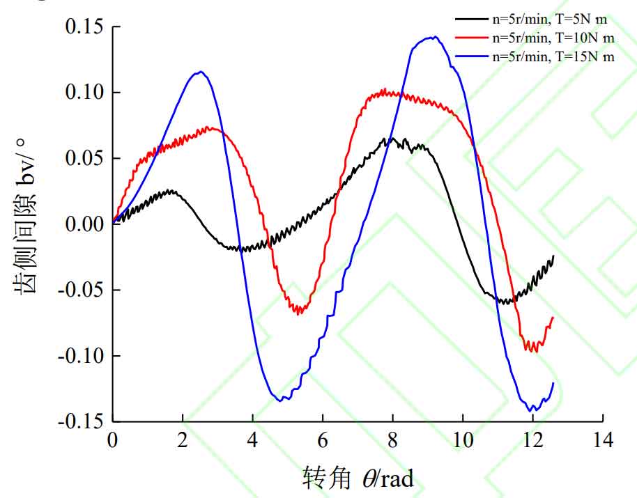
Figure 4 shows the variation trend of the side clearance of non-circular gear with load based on the bidirectional transmission error. The tooth side clearance curve in the figure shows a periodic change trend under the three load conditions. Compared with the tooth side clearance obtained by theoretical analysis, there are certain impacts and fluctuations on the tooth side clearance curve obtained by the transmission test, which indicates that there is a large difference between the transmission errors under the two steering conditions during the meshing of non-circular gear pairs. However, compared with the theoretical analysis, the tooth side clearance curve in Figure 4 shows an increasing trend in each cycle, and there is a cumulative value parameter of the tooth side clearance in the adjacent cycles. This is because during the transmission test, the distortion between the transmission elements (bearings, transmission shafts, gears) and the elasticity between the tooth profiles of non-circular gears increase, resulting in changes in the center distance and tooth side clearance. As the load increases, the difference between the two adjacent cycles gradually decreases, but it is not eliminated. The reason is that with the increase of the load, the elasticity between the teeth gradually dominates, and the tooth shape error cancels each other, which reduces the transmission error under the two kinds of steering, so it will reduce the difference between the tooth side clearance in the adjacent two cycles.