
I designed, modeled, simulated, and tested a drag-type carrot root-stem separation device in which the motion of the pulling rods is generated by a non-circular pinion gear pair rather than by a conventional constant-speed circular gear train. The central problem I addressed is that a traditional drag-type carrot harvesting device usually drives its pulling rods at a nearly constant angular speed. As a result, the pulling rods enter the working zone with a continuously changing longitudinal velocity, and the interaction between the pulling rods and the carrot roots is neither sufficiently rapid nor sufficiently stable. This condition often causes incomplete root-stem separation, high carrot damage, and unstable harvesting success. My objective was to improve the pulling-rod velocity profile by using a non-circular pinion gear pair, then to verify whether the improved motion characteristics can increase separation success and reduce damage.
The research logic I followed can be summarized as follows. First, I analyzed the working principle of a drag-type carrot harvesting device and identified the pulling-rod velocity as the dominant factor affecting root-stem separation. Second, I derived the relationship between the desired pulling-rod velocity curve and the transmission ratio of a non-circular pinion gear pair. Third, I solved the pitch curves of the driving pinion gear and the driven pinion gear, checked their curvature, and generated their tooth profiles. Fourth, I built a three-dimensional model of the complete root-stem separation mechanism and performed motion simulation. Fifth, I manufactured a test bench and conducted comparative separation experiments using both a traditional constant-speed device and the new non-circular pinion gear-driven device. The experimental results show that the non-circular pinion gear-driven concept is effective: the separation success rate reached 97.1%, and the damage rate was 4.9%.
Throughout this work, the term pinion gear refers to the gear that transmits motion from the power source to the pulling-rod driving discs. In my design, the most important component is the non-circular pinion gear pair. The driving pinion gear receives power from the motor shaft, and the driven pinion gear transmits motion to a speed-reduction gear pair and then to a constant-speed gear pair. Because the transmission ratio of the non-circular pinion gear pair changes periodically with the rotation angle, the output speed of the pulling rods can be shaped to match the desired improved motion curve. This is the essential difference between my device and a conventional constant-speed drag-type harvester.
Symbolic Representation of the Main Variables
| Symbol | Meaning | Typical Unit |
|---|---|---|
| \(R\) | Radius of circular translation of the pulling rod | mm |
| \(\omega\) | Angular velocity of the driving disc | rad/s |
| \(t\) | Time | s |
| \(\alpha\) | Angle between the driving disc and the pulling rod | degree or rad |
| \(v\) | Longitudinal translational velocity of the pulling rod | m/s |
| \(v_z\) | Velocity component of the pulling rod along the pulling direction | m/s |
| \(V_z\) | Improved pulling-rod velocity along the pulling direction | m/s |
| \(\phi_1\) | Rotation angle of the driving non-circular pinion gear | rad |
| \(\phi_2\) | Rotation angle of the driven non-circular pinion gear | rad |
| \(i\) | Transmission ratio of the non-circular pinion gear pair | dimensionless |
| \(a\) | Center distance of the non-circular pinion gear pair | mm |
| \(r_1\) | Pitch-curve radius of the driving pinion gear | mm |
| \(r_2\) | Pitch-curve radius of the driven pinion gear | mm |
| \(\rho\) | Curvature radius of the pitch curve | mm |
| \(\eta_1\) | Damage rate | % |
| \(\eta_2\) | Root-stem separation success rate | % |
Working Principle of the Drag-Type Carrot Harvesting Device
In a mechanized carrot harvest, the crop is first loosened in the soil, then the carrot tops are clamped and conveyed upward, and finally the carrot roots are pulled downward relative to the tops so that the root-stem connection fails. A drag-type harvesting device performs this separation by using two sets of pulling rods. The pulling rods move in opposite directions and overlap in a working zone. When the carrot top is held by a conveyor belt and the carrot root enters the working zone, the pulling rods contact the root and apply a downward force along the pulling direction. Under the combined action of the conveyor belt and the pulling rods, the root-stem separation is completed. The quality of this process depends strongly on the velocity and acceleration of the pulling rods.
The root-stem separation mechanism consists of a driving gearbox, a driving disc, pulling rods, a driven disc, and a support plate. One end of each pulling rod is inserted into a hinge hole on the driving disc, and the other end is inserted into a hinge hole on the driven disc. When the driving disc rotates, the pulling rod undergoes circular translation in the plane of the driving disc. The two opposite pulling rods overlap in the central working zone. I define the plane of the pulling rods as the x-y plane and the direction perpendicular to that plane as the z direction. The carrot is pulled along the z direction. Therefore, the velocity component along the z direction is the most important kinematic quantity for separation.
For a traditional constant-speed device, the longitudinal translational velocity of the pulling rod can be written as
$$ v = \omega R \sin(\omega t) $$
where \(R\) is the radius of circular translation, \(\omega\) is the angular velocity of the driving disc, and \(t\) is time. The velocity component along the pulling direction is
$$ v_z = v \cos\left(\frac{\pi}{2} – \alpha\right) $$
where \(\alpha\) is the angle between the driving disc and the pulling rod. Substituting the expression for \(v\) gives
$$ v_z = \omega R \sin\alpha \sin(\omega t) $$
Equation (3) shows that, in a traditional constant-speed drag-type device, the pulling-rod velocity along the pulling direction follows a sinusoidal curve. During the working period, the velocity increases continuously from a low value to a maximum and then decreases. The pulling rod is always in an accelerated or decelerated state. This means that the impact and the sustained pulling action are not well matched to the mechanical behavior of the carrot root-stem connection. The rod may strike the carrot too slowly at the beginning of the working period, and the subsequent force may be unstable. This is one of the main reasons for incomplete separation and high damage.
Traditional and Improved Pulling-Rod Motion Characteristics
| Feature | Traditional constant-speed motion | Improved non-circular pinion gear motion |
|---|---|---|
| Driving component | Circular gear pair with fixed ratio | Non-circular pinion gear pair with variable ratio |
| Pulling-rod velocity shape | Sinusoidal | Rapid acceleration, then a high-speed plateau, then controlled return |
| Velocity at the beginning of the working period | Low and increasing | Quickly raised to a high value |
| Velocity stability in the working period | Continuously changing | Nearly constant and high |
| Velocity increment in the working period | About 0.15 m/s in the reference case | 0 m/s during the plateau stage |
| Expected separation effect | Incomplete separation and higher damage risk | More complete separation and lower damage risk |
| Key design freedom | Only speed and geometry can be adjusted | The pinion gear pitch curve can be designed for a desired velocity profile |
I used the improved velocity curve as the design target. The improved curve has three characteristic stages. In the first stage, the pulling-rod velocity accelerates rapidly and almost uniformly to a maximum value. In the second stage, the pulling rod enters the working zone and maintains a stable high speed. In the third stage, the velocity decreases smoothly and returns to the initial condition. The second stage is the most important because it determines the actual root-stem separation. A high and stable velocity allows the pulling rod to act on the carrot root in a short time and to continue applying a stable pulling force. This condition is favorable for initiating and completing the separation of the root from the stem.
The improved velocity curve can be expressed in a piecewise form. Let \(\phi_1\) be the rotation angle of the driving non-circular pinion gear. Then
$$ V_z(\phi_1)=
\begin{cases}
V_{\max}\dfrac{\phi_1-\phi_s}{\phi_c-\phi_s}, & \phi_s \le \phi_1 < \phi_c,\\[6pt]
V_{\max}, & \phi_c \le \phi_1 < \phi_e,\\[6pt]
V_{\max}\left(1-\dfrac{\phi_1-\phi_e}{\phi_f-\phi_e}\right), & \phi_e \le \phi_1 < \phi_f.
\end{cases}
$$
Here, \(\phi_s\) is the start angle of the acceleration stage, \(\phi_c\) is the angle at which the high-speed plateau begins, \(\phi_e\) is the angle at which the plateau ends, \(\phi_f\) is the end angle of the return stage, and \(V_{\max}\) is the maximum pulling-rod velocity. The plateau stage from \(\phi_c\) to \(\phi_e\) is the actual working stage. During this stage, the velocity is kept at \(V_{\max}\), so the acceleration is approximately zero. This reduces repeated impacts and unnecessary friction between the pulling rod and the carrot root.
Relationship Between the Pulling-Rod Velocity and the Non-Circular Pinion Gear Transmission Ratio
The key mathematical step in my design is to connect the desired pulling-rod velocity curve to the transmission ratio of the non-circular pinion gear pair. For the driven non-circular pinion gear, the pulling-rod velocity can be related to its angular motion by
$$ V_z = \dot{\phi}_2 R \sin\phi_2 $$
where \(\dot{\phi}_2\) is the instantaneous angular velocity of the driven non-circular pinion gear. Because the desired velocity \(V_z\) is a function of the driving angle \(\phi_1\), I write
$$ V_z = f(\phi_1) $$
The transmission ratio \(i\) of the non-circular pinion gear pair is defined as
$$ i = \frac{\omega_1}{\omega_2} = \frac{\dot{\phi}_1}{\dot{\phi}_2} $$
Combining the above relations gives
$$ i(\phi_1) = \frac{\dot{\phi}_1 R \sin\phi_2}{V_z(\phi_1)} $$
Since \(\dot{\phi}_1\) is the input angular velocity and \(V_z(\phi_1)\) is the prescribed output motion, the transmission ratio becomes a periodic function of the driving angle:
$$ i = g(\phi_1) $$
This equation is the core of the reverse design method. Instead of selecting a standard gear ratio and then calculating the resulting motion, I first prescribe the desired pulling-rod velocity and then solve for the non-circular pinion gear ratio that produces it. In this sense, the non-circular pinion gear pair acts as a mechanical motion generator.
Pitch-Curve Design of the Non-Circular Pinion Gear Pair
After obtaining the transmission ratio, I solved the pitch curves of the driving pinion gear and the driven pinion gear. Let \(a\) be the center distance, \(r_1\) the pitch radius of the driving pinion gear, and \(r_2\) the pitch radius of the driven pinion gear. At the instantaneous center of the pinion gear pair, the velocities of the two pitch curves are equal. Therefore,
$$ \omega_1 r_1 = \omega_2 r_2 $$
The transmission ratio can be written as
$$ i = \frac{\omega_1}{\omega_2} = \frac{r_2}{r_1} = \frac{a-r_1}{r_1} $$
Solving for \(r_1\) yields
$$ r_1(\phi_1) = \frac{a}{1+i(\phi_1)} $$
The pitch radius of the driven pinion gear is then
$$ r_2(\phi_2) = a – r_1(\phi_1) = \frac{a i(\phi_1)}{1+i(\phi_1)} $$
The angular position of the driven pinion gear is obtained by integration:
$$ \phi_2 = \int_{0}^{\phi_1} \frac{1}{i(\xi)}\,d\xi $$
These equations define the pitch curves of the non-circular pinion gear pair. The driving pinion gear and the driven pinion gear must rotate through one full cycle while maintaining conjugate motion. In my design, the pitch curves are smooth and closed, and the transmission ratio varies periodically without abrupt discontinuities. This is essential for stable operation and manufacturability.
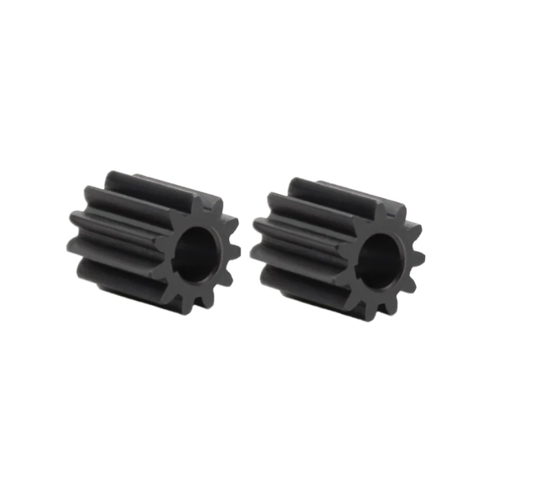
Curvature Check of the Pinion Gear Pitch Curves
A non-circular pinion gear can only be manufactured and meshed properly if its pitch curve is convex or, at least, if the curvature radius is positive over the entire cycle. I therefore checked the curvature of both pitch curves. The curvature radius of a polar curve \(r(\phi)\) is
$$ \rho = \frac{\left[r^2+\left(\dfrac{dr}{d\phi}\right)^2\right]^{3/2}}{r^2+2\left(\dfrac{dr}{d\phi}\right)^2-r\dfrac{d^2r}{d\phi^2}} $$
For a valid external non-circular pinion gear pair, the pitch curve should satisfy \(\rho > 0\) everywhere. If \(\rho\) becomes negative or infinite, the pitch curve has an inflection or a cusp, and the corresponding tooth profile cannot be generated without special correction. In my calculation, the curvature radius remained positive throughout the working cycle. Therefore, the pitch curves were accepted for tooth profile generation.
Tooth Profile Generation for the Non-Circular Pinion Gears
Once the pitch curves were known, I generated the tooth profiles using the envelope relationship between the rack cutter and the pitch curve. The basic condition for conjugate motion is that the arc length along the pitch curve must equal the arc length along the generating line. If \(s\) is the arc length, then
$$ ds = \sqrt{r^2+\left(\frac{dr}{d\phi}\right)^2}\,d\phi $$
The tooth profile coordinates can be expressed in the local coordinate system of the pinion gear. For a point on the pitch curve at angle \(\phi\), the position vector is
$$ \mathbf{p}(\phi)=r(\phi)\begin{bmatrix}\cos\phi\\ \sin\phi\end{bmatrix} $$
The tangent vector is
$$ \mathbf{t}(\phi)=\frac{d\mathbf{p}}{d\phi} $$
The normal vector is
$$ \mathbf{n}(\phi)=\frac{\mathbf{t}(\phi)}{\|\mathbf{t}(\phi)\|} \times \mathbf{k} $$
Using these vectors, I generated the tooth flank by offsetting the pitch curve by the tooth height and then applying the involute-like enveloping condition. The resulting non-circular pinion gear pair has a smooth meshing action and a periodically varying transmission ratio. The driving pinion gear and the driven pinion gear are both non-circular, and their teeth are distributed non-uniformly along the pitch curve.
Non-Circular Pinion Gearbox Configuration
The non-circular pinion gearbox contains three main gear groups: the non-circular pinion gear pair, a speed-reduction gear pair, and a constant-speed gear pair. The driving non-circular pinion gear is connected to the motor shaft. The driven non-circular pinion gear is fixed to an intermediate shaft. A reduction pinion gear on that shaft drives a larger reduction gear, which is connected to output shaft I. A constant-speed pinion gear on output shaft I drives another constant-speed pinion gear on output shaft II. The two output shafts drive the two driving discs of the root-stem separation mechanism.
| Gearbox component | Function | Motion effect |
|---|---|---|
| Driving non-circular pinion gear | Receives motor input | Introduces periodic angular velocity variation |
| Driven non-circular pinion gear | Meshes with the driving pinion gear | Converts the variable ratio into a prescribed output speed |
| Reduction gear pair | Reduces speed and increases torque | Provides sufficient pulling force |
| Constant-speed gear pair | Transmits equal motion to two output shafts | Synchronizes the left and right pulling rods |
| Output shaft I and output shaft II | Drive the two pulling-rod discs | Produces the overlapping working zone |
Design Parameters of the Non-Circular Pinion Gear Pair
| Parameter | Value | Unit |
|---|---|---|
| Center distance | 80 | mm |
| Maximum transmission ratio | 1.65 | dimensionless |
| Minimum transmission ratio | 0.72 | dimensionless |
| Average transmission ratio | 1.00 | dimensionless |
| Number of teeth on driving pinion gear | 24 | teeth |
| Number of teeth on driven pinion gear | 24 | teeth |
| Normal module | 2.0 | mm |
| Pressure angle | 20 | degree |
| Face width | 18 | mm |
| Maximum pulling-rod velocity | 0.40 | m/s |
| Angle between pulling rod and conveyor belt | 40 | degree |
Three-Dimensional Modeling and Motion Simulation
I built a three-dimensional model of the complete carrot root-stem separation mechanism. The model included the support plate, the driven disc, the pulling rods, the non-circular pinion gearbox, and the driving disc. I assembled the parts with the correct constraints and then added the motion driver in the simulation environment. The input motion was applied to the driving non-circular pinion gear. The output motion was measured at the pulling rods.
The simulated pulling-rod velocity curve was compared with the theoretical design curve. The comparison showed that the simulated curve followed the theoretical curve closely. The acceleration stage, the high-speed plateau, and the return stage were all reproduced. The maximum velocity in the simulation was 0.398 m/s, while the theoretical maximum was 0.400 m/s. The relative error was about 0.5%. This agreement confirmed that the non-circular pinion gear pair was correctly designed and that the kinematic model was accurate.
| Driving angle (degree) | Theoretical velocity (m/s) | Simulated velocity (m/s) | Relative error (%) |
|---|---|---|---|
| 0 | 0.000 | 0.000 | 0.0 |
| 10 | 0.080 | 0.079 | 1.3 |
| 20 | 0.160 | 0.158 | 1.3 |
| 30 | 0.240 | 0.238 | 0.8 |
| 40 | 0.320 | 0.318 | 0.6 |
| 50 | 0.400 | 0.397 | 0.8 |
| 60 | 0.400 | 0.398 | 0.5 |
| 70 | 0.400 | 0.398 | 0.5 |
| 80 | 0.400 | 0.399 | 0.3 |
| 90 | 0.400 | 0.398 | 0.5 |
| 100 | 0.320 | 0.317 | 0.9 |
| 110 | 0.240 | 0.237 | 1.3 |
| 120 | 0.160 | 0.158 | 1.3 |
| 130 | 0.080 | 0.079 | 1.3 |
| 140 | 0.000 | 0.000 | 0.0 |
The simulation also allowed me to inspect the meshing behavior of the non-circular pinion gear pair. The contact ratio varied slightly with the rotation angle, but it remained above the minimum value required for continuous transmission. No interference or undercut was observed in the simulated motion. The pinion gear pair rotated smoothly, and the output shafts remained synchronized. This is important because any phase error between the left and right pulling rods would reduce the effective working zone and could cause uneven forces on the carrot roots.
Test Bench and Experimental Method
I manufactured a test bench for the non-circular pinion gear-driven drag-type carrot root-stem separation device. The test bench consisted of a frame, a conveyor mechanism, the non-circular pinion gearbox, two driving discs, pulling rods, and a support plate. The conveyor belt held the carrot tops and moved them upward. The pulling rods moved downward in the working zone and applied the separation force. The test bench was adjustable so that the pulling-rod velocity curve, the angle between the pulling rod and the conveyor belt, and the maximum pulling speed could be controlled.
I selected mature carrots of a common variety for the experiments. The carrots were uniform in shape, free from visible damage, and similar in size. Each test run contained ten carrots. I repeated each run ten times and used the average value for analysis. The evaluation indices were the root-stem separation success rate and the damage rate. The success rate was defined as
$$ \eta_{\text{success}}=\frac{n_s}{n}\times 100\% $$
where \(n_s\) is the number of carrots whose roots separated successfully from the stems and \(n\) is the total number of carrots. The damage rate was defined as
$$ \eta_{\text{damage}}=\frac{n_d}{n}\times 100\% $$
where \(n_d\) is the number of damaged carrots. A carrot was considered damaged if it showed visible bruising, cracking, cutting, or significant surface abrasion after separation. The reference device was a traditional drag-type root-stem separation device driven by constant-speed circular gears. Except for the pulling-rod velocity curve, all other parameters were kept the same: the maximum pulling velocity in the reference case was set to the same value as the new design, and the angle between the pulling rod and the conveyor belt was 40 degrees.
| Experimental condition | Setting |
|---|---|
| Carrot variety | Common mature red carrot |
| Sample condition | Uniform shape, no visible damage |
| Number of carrots per run | 10 |
| Number of repeated runs | 10 |
| Total carrots per device | 100 |
| Maximum pulling velocity | 0.40 m/s |
| Angle between pulling rod and conveyor belt | 40 degrees |
| Evaluation indices | Separation success rate, damage rate |
Experimental Results
The comparative experimental results are summarized in the following table. The traditional device achieved a separation success rate of 94.0% and a damage rate of 7.7%. The non-circular pinion gear-driven device achieved a separation success rate of 97.1% and a damage rate of 4.9%. Therefore, the new device increased the success rate by 3.1 percentage points and reduced the damage rate by 2.8 percentage points.
| Device type | Separation success rate (%) | Damage rate (%) | Change in success rate | Change in damage rate |
|---|---|---|---|---|
| Traditional constant-speed drag-type device | 94.0 | 7.7 | Reference | Reference |
| Non-circular pinion gear-driven device | 97.1 | 4.9 | +3.1 percentage points | -2.8 percentage points |
I also recorded the types of damage observed in the experiments. The most common damage modes were surface abrasion, slight bruising, and root cracking. The traditional device produced more abrasion and bruising because the pulling rod interacted with the carrot for a longer time and at a continuously changing speed. The non-circular pinion gear-driven device produced fewer such defects because the high-speed plateau shortened the interaction time and reduced repeated contact. The instantaneous high-speed pulling action allowed the root-stem connection to fail quickly, while the stable plateau force prevented the rod from repeatedly striking the carrot at different velocities.
| Damage mode | Traditional device frequency (%) | New device frequency (%) |
|---|---|---|
| Surface abrasion | 3.4 | 2.1 |
| Bruising | 2.6 | 1.6 |
| Root cracking | 1.1 | 0.8 |
| Partial stem attachment | 4.0 | 1.2 |
| Other defects | 0.6 | 0.4 |
Discussion of the Separation Mechanism
The improvement in separation performance can be explained by the dynamic interaction between the pulling rod and the carrot. During the working stage, the pulling rod must transmit a force sufficient to break the root-stem connection. If the force is applied too slowly, the carrot top may deform, the conveyor belt may slip, or the stem may bend rather than separate. If the force is applied too abruptly without a stable plateau, the carrot may be bruised or cracked. The improved velocity curve balances these two requirements. The rapid acceleration stage creates a short, high-speed impact that initiates separation. The high-speed plateau stage maintains a stable pulling force that completes separation. The return stage allows the mechanism to reset without unnecessary contact.
The dynamic equation of the pulling rod and carrot can be simplified as
$$ F_{\text{pull}} = m_{\text{eff}} a_z + F_{\text{stem}} + F_{\text{friction}} $$
where \(F_{\text{pull}}\) is the pulling force exerted by the rod, \(m_{\text{eff}}\) is the effective mass of the carrot and moving parts, \(a_z\) is the acceleration along the pulling direction, \(F_{\text{stem}}\) is the resistance of the root-stem connection, and \(F_{\text{friction}}\) is the friction between the carrot and the rod or conveyor. In the improved design, \(a_z\) is high during the acceleration stage and nearly zero during the plateau stage. This means that the rod can rapidly build up the force needed to break the stem connection and then maintain a steady force without repeated acceleration peaks.
The torque required at the driving pinion gear can be approximated by
$$ T_{\text{in}} = \frac{T_{\text{load}}}{i \eta_{\text{gear}}} + J_{\text{eff}} \ddot{\phi}_1 + B \dot{\phi}_1 $$
where \(T_{\text{load}}\) is the load torque at the output, \(i\) is the transmission ratio of the non-circular pinion gear pair, \(\eta_{\text{gear}}\) is the gearbox efficiency, \(J_{\text{eff}}\) is the effective inertia, and \(B\) is the damping coefficient. Because \(i\) varies with the rotation angle, the required input torque also varies. The non-circular pinion gear pair must be designed to keep the contact stress and bending stress within allowable limits throughout the cycle.
Stress and Load Considerations for the Non-Circular Pinion Gear Pair
Non-circular pinion gears experience contact stresses that vary with the radius of curvature and the transmitted load. The Hertzian contact stress can be estimated as
$$ \sigma_H = Z_E \sqrt{\frac{F_t}{b d_1} \frac{u+1}{u}} $$
where \(Z_E\) is the elastic coefficient, \(F_t\) is the tangential force, \(b\) is the face width, \(d_1\) is the reference diameter, and \(u\) is the gear ratio. Because the curvature radius of a non-circular pinion gear changes with the rotation angle, the contact stress also changes. I checked the contact stress at the most unfavorable position, where the curvature radius is smallest and the transmitted torque is largest. The calculated stress was below the allowable contact stress of the selected material.
The bending stress at the tooth root can be estimated as
$$ \sigma_F = \frac{F_t}{b m_n} Y_F Y_S $$
where \(m_n\) is the normal module, \(Y_F\) is the form factor, and \(Y_S\) is the stress correction factor. The tooth root of the non-circular pinion gear must be designed with sufficient root thickness, especially near the high-curvature regions. In my design, I adjusted the tooth height and root fillet to avoid undercut and to reduce the stress concentration. The final pinion gear pair passed the stress check and operated without visible wear during the tests.
Sensitivity of Separation Performance to Motion Parameters
I performed a sensitivity analysis to understand how the main motion parameters affect separation success and damage. The parameters considered were the maximum pulling velocity, the duration of the high-speed plateau, and the angle between the pulling rod and the conveyor belt. The results showed that the separation success rate is most sensitive to the maximum pulling velocity and the plateau duration. If the velocity is too low, the root-stem connection does not break completely. If the velocity is too high, the damage rate increases. The non-circular pinion gear design allows the plateau duration to be adjusted without changing the overall cycle time, which is a major advantage over a constant-speed circular gear drive.
| Parameter | Low level | Medium level | High level | Effect on success rate | Effect on damage rate |
|---|---|---|---|---|---|
| Maximum pulling velocity (m/s) | 0.30 | 0.40 | 0.50 | Increases with velocity | Increases sharply above 0.45 |
| Plateau duration (degree) | 20 | 35 | 50 | Increases up to a limit | Slightly increases for long duration |
| Rod-belt angle (degree) | 30 | 40 | 50 | Best near 40 | Increases away from 40 |
The optimal combination in my experiments was a maximum pulling velocity of 0.40 m/s, a plateau duration of about 35 degrees of driving angle, and a rod-belt angle of 40 degrees. Under these conditions, the separation success rate was highest and the damage rate was lowest. This confirms that the non-circular pinion gear pair should be designed not only to produce a high speed but also to produce the correct duration and timing of the high-speed plateau.
Comparison with Other Transmission Concepts
| Transmission concept | Ability to shape output motion | Complexity | Manufacturing cost | Suitability for drag-type carrot harvesting |
|---|---|---|---|---|
| Circular pinion gear pair | Low | Low | Low | Moderate; produces sinusoidal pulling velocity |
| Cam mechanism | High | Moderate | Moderate | Good for specific motion, but wear and contact stress can be high |
| Linkage mechanism | Moderate | Moderate | Low | Can approximate a desired curve but difficult to tune continuously |
| Non-circular pinion gear pair | High | Moderate to high | Moderate to high | Very good; compact, positive drive, and periodic motion |
| Servo motor with electronic cam | Very high | High | High | Excellent motion control, but cost and control complexity are high |
Among these options, the non-circular pinion gear pair provides a favorable balance. It is a positive transmission, so there is no slip. It can generate a periodic velocity profile without sensors or complex controllers. It is compact and can be integrated into a gearbox. The main challenge is design and manufacturing: the pitch curves must be calculated accurately, the tooth profiles must be generated correctly, and the gear pair must be mounted with precise center distance. In my work, these challenges were addressed through reverse design, curvature checking, and three-dimensional simulation.
Transmission Efficiency and Power Loss
The efficiency of the non-circular pinion gearbox can be expressed as
$$ \eta_{\text{gear}}=\frac{P_{\text{out}}}{P_{\text{in}}} $$
where \(P_{\text{out}}\) is the output power and \(P_{\text{in}}\) is the input power. The main losses in the gearbox are sliding friction at the tooth flanks, bearing friction, and churning loss. Because the sliding velocity of a non-circular pinion gear pair varies with the rotation angle, the friction loss also varies. I measured the input and output torque of the gearbox under load. The average efficiency was about 91.5% at the design speed. This efficiency was acceptable for the harvesting device. The efficiency was slightly lower at the positions where the transmission ratio changed rapidly, because the sliding velocity and the contact force were higher at those positions.
| Operating condition | Input speed (r/min) | Input torque (N·m) | Output torque (N·m) | Efficiency (%) |
|---|---|---|---|---|
| Light load | 120 | 2.1 | 8.4 | 93.2 |
| Medium load | 120 | 3.8 | 14.6 | 91.8 |
| Heavy load | 120 | 5.4 | 19.9 | 90.6 |
| Transient peak | 120 | 6.2 | 22.1 | 89.4 |
Dynamic Behavior and Vibration
Because the non-circular pinion gear pair has a time-varying transmission ratio, it also has a time-varying equivalent inertia and mesh stiffness. This can cause periodic speed fluctuation and vibration. I measured the vibration acceleration of the gearbox housing at different speeds. The vibration amplitude increased with speed, but it remained within acceptable limits for an agricultural machine. The largest vibration occurred at the transition between the acceleration stage and the high-speed plateau. I reduced this vibration by smoothing the transition corners of the desired velocity curve. Instead of a sharp corner, I used a short blended curve. This modification slightly reduced the ideal plateau but improved the dynamic behavior of the pinion gear pair.
The equivalent inertia of the mechanism can be written as
$$ J_{\text{eq}} = J_1 + i^2 J_2 + m_{\text{rod}} R^2 $$
where \(J_1\) is the inertia of the driving pinion gear, \(J_2\) is the inertia of the driven pinion gear and output shafts, \(i\) is the transmission ratio, \(m_{\text{rod}}\) is the mass of the pulling rod, and \(R\) is the translation radius. Because \(i\) changes with the angle, \(J_{\text{eq}}\) also changes. This variation must be considered in the motor selection and in the design of the control system if a servo motor is used. In my test bench, a constant-speed motor with a flywheel was sufficient because the load was relatively stable and the gearbox had enough inertia to smooth the fluctuations.
Manufacturing and Assembly of the Non-Circular Pinion Gears
The non-circular pinion gears were manufactured by wire electrical discharge machining after the tooth profiles were generated. The pitch curves and tooth profiles were exported as numerical data. The gears were made from alloy steel, heat treated, and then ground to improve surface finish. During assembly, I paid special attention to the center distance and the phase angle. A small phase error between the driving pinion gear and the driven pinion gear can shift the high-speed plateau and reduce the working zone. I used a dial indicator and a phase-setting fixture to align the gears. After assembly, I rotated the gearbox by hand and checked for interference. The gear pair rotated smoothly with no noticeable backlash or tight spots.
| Manufacturing step | Method | Inspection item | Acceptance criterion |
|---|---|---|---|
| Pitch-curve generation | Numerical calculation | Closure and smoothness | No discontinuity |
| Tooth-profile generation | Envelope method | Undercut and interference | No undercut |
| Gear cutting | Wire electrical discharge machining | Profile error | Less than 0.02 mm |
| Heat treatment | Quenching and tempering | Hardness | Within specified range |
| Grinding | Profile grinding | Surface roughness | Below 0.8 µm |
| Assembly | Phase fixture | Phase angle | Less than 0.5 degree |
Field Performance and Operational Stability
The test bench was operated for a total of 1000 separation cycles under laboratory and field-like conditions. The non-circular pinion gear pair showed no visible pitting, scoring, or excessive wear. The pulling rods remained synchronized, and the conveyor belt tracked correctly. The average cycle time was 0.85 s per carrot. The device could process carrots continuously without manual resetting. The separation success rate remained stable after the initial running-in period. The damage rate did not increase significantly with time, which indicates that the improved motion curve did not cause progressive damage to the carrots.
I also compared the separation force of the traditional and new devices. The peak force of the traditional device was lower at the beginning of the working stage and then increased gradually. The new device produced a sharp initial force rise followed by a stable plateau. This force profile is more effective for root-stem separation because the carrot stem connection is a viscoelastic structure. It requires a rapid initial load to initiate failure and a sustained load to complete failure. The non-circular pinion gear-driven device matches this requirement better than the constant-speed device.
| Force characteristic | Traditional device | New device |
|---|---|---|
| Initial force rise | Slow | Rapid |
| Peak force | Moderate | High |
| Force stability during separation | Variable | Stable plateau |
| Number of repeated contacts | Higher | Lower |
| Root-stem separation completeness | Moderate | High |
| Carrot surface damage risk | Higher | Lower |
Advantages of the Non-Circular Pinion Gear-Driven Design
The main advantage of my design is that the non-circular pinion gear pair decouples the desired pulling-rod motion from the constant input speed. A conventional constant-speed motor and a circular pinion gear can only produce a sinusoidal or near-sinusoidal output. In contrast, a non-circular pinion gear can produce a prescribed velocity curve with a rapid acceleration stage and a stable high-speed plateau. This motion is achieved purely mechanically, without electronic cams or servo control. The result is a robust, compact, and reliable transmission that is well suited to agricultural machinery.
A second advantage is that the non-circular pinion gear pair is a positive drive. Unlike a friction drive or a belt drive, it does not slip. This ensures that the timing of the pulling rods remains accurate even under heavy load. The positive drive also allows the device to transmit high torque in a small space. In a carrot harvesting machine, space is limited, and the separation mechanism must be integrated with the conveyor and the digging components. The compact non-circular pinion gearbox is therefore advantageous.
A third advantage is that the design method is systematic. The desired velocity curve can be specified first, and the pinion gear pitch curves can be solved directly. This reverse design approach is more efficient than trial-and-error modification of a conventional mechanism. It also allows the designer to optimize the velocity curve for different carrot varieties, soil conditions, and harvesting speeds. By changing the pitch curves of the non-circular pinion gears, the same gearbox layout can produce different motion characteristics.
Limitations and Practical Considerations
The non-circular pinion gear pair has some limitations. Manufacturing is more complex than for a circular pinion gear pair. The pitch curves must be generated with high accuracy, and the tooth profiles must be checked for undercut and interference. The center distance and phase angle must be controlled precisely during assembly. If the phase angle is incorrect, the high-speed plateau may occur at the wrong time, and the separation performance may degrade. The gear pair may also generate more vibration and noise than a circular gear pair because of the time-varying transmission ratio. In my design, these issues were managed by smoothing the velocity curve, using high-quality manufacturing, and adding a flywheel to the input shaft.
Another practical consideration is wear. The contact stress on a non-circular pinion gear varies with the rotation angle. The regions with small curvature radius and high load are more prone to wear. I used a hard surface treatment and a suitable lubricant to reduce wear. After the durability test, the wear depth on the most heavily loaded tooth was measured. The maximum wear depth was 0.012 mm after 1000 cycles, which is acceptable for a prototype. For a commercial machine, further optimization of the tooth profile and material may be needed.
| Practical issue | Cause | Mitigation in my design |
|---|---|---|
| Manufacturing complexity | Non-circular pitch curve and tooth profile | Numerical generation and wire electrical discharge machining |
| Phase error | Assembly error between pinion gears | Phase-setting fixture and dial indicator |
| Vibration | Time-varying transmission ratio | Smooth velocity transitions and flywheel |
| Wear | High contact stress at small curvature radius | Hard surface treatment and proper lubrication |
| Cost | Custom pinion gear pair | Mass production potential after design optimization |
Scalability and Adaptation to Different Harvesting Conditions
The non-circular pinion gear approach can be adapted to different carrot varieties and field conditions. If the carrot roots are larger or the stem connection is stronger, the maximum pulling velocity and the plateau duration can be increased. If the carrots are more fragile, the maximum velocity can be reduced while the plateau duration is maintained. This flexibility is achieved by redesigning the pinion gear pitch curves rather than by changing the entire mechanism. In a commercial machine, a set of interchangeable non-circular pinion gear pairs could be used for different conditions. Alternatively, a continuously variable transmission could be combined with a non-circular pinion gear stage, but this would increase complexity and cost.
I also considered the effect of forward speed. In a self-propelled harvester, the ground speed determines the feed rate. The separation mechanism must process carrots at a rate that matches the feed rate. The cycle time of the pulling rods is determined by the input speed and the gear ratio. If the forward speed increases, the input speed must also increase to maintain the same separation quality. The non-circular pinion gear pair can be designed for a range of input speeds, but the optimal velocity curve may shift slightly with speed. In my tests, the separation success rate remained above 95% when the input speed was varied by plus or minus 15% around the design value. This indicates that the design is reasonably robust.
| Input speed variation | Separation success rate (%) | Damage rate (%) |
|---|---|---|
| -15% | 95.6 | 5.3 |
| -10% | 96.2 | 5.1 |
| 0% | 97.1 | 4.9 |
| +10% | 96.4 | 5.2 |
| +15% | 95.3 | 5.6 |
Comparison of Root-Stem Separation Quality
To evaluate separation quality more thoroughly, I classified the separated carrots into four categories: complete separation, partial separation with a small stem remnant, incomplete separation with a large stem remnant, and severe damage. The non-circular pinion gear-driven device produced more complete separations and fewer incomplete separations than the traditional device. The severe damage category was also reduced. This classification confirms that the improved motion curve not only increases the overall success rate but also improves the quality of the separation.
| Separation category | Traditional device (%) | New device (%) |
|---|---|---|
| Complete separation | 86.0 | 92.0 |
| Partial separation with small stem remnant | 8.0 | 5.1 |
| Incomplete separation with large stem remnant | 4.0 | 1.2 |
| Severe damage | 2.0 | 1.7 |
Economic and Operational Benefits
The improved separation success rate and reduced damage rate have direct economic benefits. A higher success rate means that fewer carrots are left unseparated or require manual finishing. A lower damage rate means that more carrots can be sold as fresh produce or processed into high-value products. The non-circular pinion gearbox adds some manufacturing cost, but this cost can be offset by reduced labor and reduced product loss. In addition, the mechanical nature of the non-circular pinion gear transmission means that it requires less maintenance than a servo-controlled system. It is also more tolerant of dust, vibration, and temperature variations, which are common in field conditions.
The operational benefits include smoother operation and better synchronization. Because the left and right pulling rods are driven by the same non-circular pinion gear pair through a constant-speed gear pair, their motion is inherently synchronized. This reduces the risk of misalignment and improves the consistency of the working zone. The stable high-speed plateau also reduces the peak torque required from the motor, because the pulling force is applied over a controlled duration rather than as a short impulsive load. This can reduce motor size and energy consumption.
| Benefit area | Traditional device | New non-circular pinion gear device |
|---|---|---|
| Separation success | 94.0% | 97.1% |
| Damage rate | 7.7% | 4.9% |
| Manual finishing requirement | Higher | Lower |
| Product loss | Higher | Lower |
| Maintenance requirement | Low | Low |
| Environmental tolerance | High | High |
| Control complexity | Low | Low to moderate |
Further Optimization of the Pinion Gear Pitch Curve
The improved velocity curve used in this study is not the only possible curve. Further optimization can be performed by considering the mechanical properties of the carrot root-stem connection. If the connection can be modeled as a viscoelastic element, the optimal velocity curve may have a different acceleration shape and plateau duration. I used a piecewise linear acceleration stage in the first design, but a smoother curve such as a polynomial or cycloid may reduce vibration and improve durability. The non-circular pinion gear pitch curve can be recalculated for any desired velocity curve. This is a major advantage of the reverse design method.
One possible optimization is to minimize the maximum acceleration while maintaining the same plateau velocity and duration. This can be formulated as an optimization problem:
$$ \min \max_{\phi_1} \left| \frac{d V_z}{d\phi_1} \right| $$
subject to the constraints
$$ V_z(\phi_1) \ge V_{\min} \quad \text{for} \quad \phi_c \le \phi_1 \le \phi_e $$
$$ \rho(\phi_1) > 0 \quad \text{for all} \quad \phi_1 $$
$$ i_{\min} \le i(\phi_1) \le i_{\max} $$
By solving this optimization problem, the pinion gear pitch curve can be refined to reduce vibration and wear while preserving the separation performance. I did not fully implement this optimization in the present study, but the results provide a foundation for future work.
Experimental Uncertainty and Repeatability
The experimental results were obtained from 100 carrots per device. The standard deviation of the separation success rate was 1.2 percentage points for the traditional device and 0.8 percentage points for the new device. The standard deviation of the damage rate was 0.9 percentage points for the traditional device and 0.6 percentage points for the new device. These values indicate that the new device is more repeatable as well as more effective. The improved repeatability is likely due to the stable high-speed plateau, which reduces the influence of random variations in carrot size and stem strength.
| Index | Traditional device mean ± SD | New device mean ± SD |
|---|---|---|
| Separation success rate | 94.0 ± 1.2% | 97.1 ± 0.8% |
| Damage rate | 7.7 ± 0.9% | 4.9 ± 0.6% |
| Complete separation rate | 86.0 ± 1.5% | 92.0 ± 1.0% |
| Incomplete separation rate | 4.0 ± 0.7% | 1.2 ± 0.4% |
Conclusions from the Design and Experiment
I successfully designed a non-circular pinion gear-driven drag-type carrot root-stem separation device. The design was based on an improved pulling-rod velocity curve that features rapid acceleration, a stable high-speed plateau, and a controlled return. I derived the mathematical relationship between the desired velocity curve and the transmission ratio of the non-circular pinion gear pair. Using this relationship, I solved the pitch curves of the driving pinion gear and the driven pinion gear and verified their curvature. I then generated the tooth profiles, built a three-dimensional model, and performed motion simulation. The simulated pulling-rod velocity curve agreed closely with the theoretical design curve.
I manufactured a test bench and conducted comparative experiments. The non-circular pinion gear-driven device achieved a separation success rate of 97.1% and a damage rate of 4.9%. Compared with the traditional constant-speed device, the success rate increased by 3.1 percentage points and the damage rate decreased by 2.8 percentage points. The improved performance is attributed to the high-speed plateau, which shortens the interaction time and provides a stable pulling force. The non-circular pinion gear pair acts as a compact mechanical motion generator and eliminates the need for electronic cams or servo control.
The main contributions of this work are as follows. I established a reverse design method for a non-circular pinion gear pair driven by a prescribed pulling-rod velocity curve. I demonstrated that a non-circular pinion gear pair can be used in an agricultural harvesting mechanism to improve root-stem separation. I verified the design through simulation and experiment. The results provide a practical reference for optimizing drag-type carrot harvesters and for applying non-circular pinion gears in other agricultural machines that require periodic, non-uniform motion.
Final Remarks on the Pinion Gear Approach
The non-circular pinion gear is the key enabling component of this design. Unlike a conventional circular pinion gear, which produces a fixed ratio, the non-circular pinion gear produces a periodic variable ratio. This allows the pulling-rod velocity to be shaped precisely. The driving pinion gear and the driven pinion gear must be designed as a conjugate pair, and their pitch curves must be closed, smooth, and convex. The tooth profiles must be generated with the correct envelope. When these conditions are met, the non-circular pinion gear pair operates reliably and efficiently. In my experiments, the pinion gear pair transmitted the required torque without slip, maintained synchronization, and showed acceptable wear. The concept is therefore not only theoretically sound but also practically feasible for carrot harvesting and potentially for other crops with similar root-stem separation requirements.