
I have focused my research on non-orthogonal asymmetric helical face gears because they offer variable shaft angles and asymmetric pressure angles on the two flanks. These face gears are widely used in high-precision aviation equipment. My goal is to provide an accurate design theory and a practical engineering solution for the tooth surface design and tooth stiffness calculation of such face gears. In this work, I establish the meshing equations, solve them to obtain the tooth surface morphology, calculate the time-varying meshing stiffness under different pressure angles and shaft angles using an improved potential energy method, and verify the results with finite element simulation. The results show that increasing the pressure angle or reducing the shaft angle can significantly improve the time-varying meshing stiffness of non-orthogonal asymmetric helical face gears.
Previous studies have explored face gear drives with involute helical pinions, tooth root bending stress, and mesh stiffness calculation using potential energy methods. Some researchers have investigated non-orthogonal asymmetric helical face gear design and modeling. However, there is still a lack of research on the tooth surface design of non-orthogonal asymmetric helical face gears, especially regarding the influence of pressure angle and shaft angle on time-varying meshing stiffness. Therefore, I propose a method to calculate the time-varying meshing stiffness of non-orthogonal asymmetric helical face gears and investigate the influence mechanism of pressure angle and shaft angle. I verify my calculations through finite element simulation. This work provides theoretical guidance and technical support for the design of non-orthogonal asymmetric helical face gears to meet the increasingly stringent requirements of modern industrial gear transmission systems.
1 Design of Non-Orthogonal Asymmetric Helical Face Gear
1.1 Machining Coordinate Systems
The tooth surface of a face gear is generated by the envelope of the shaper cutter tooth surface. I establish a series of coordinate systems to derive the tooth surface. Let \(S_1(x_1,y_1,z_1)\) be the rotating coordinate system of the non-orthogonal asymmetric helical face gear. Let \(S_2(x_2,y_2,z_2)\) be the fixed coordinate system of the face gear. Let \(S_p(x_p,y_p,z_p)\) be the rotating coordinate system of the asymmetric helical gear shaper cutter. Let \(S_a(x_a,y_a,z_a)\) and \(S_b(x_b,y_b,z_b)\) be auxiliary coordinate systems. The transformation matrix from the shaper cutter fixed coordinate system to its rotating coordinate system is:
$$ M_{p,2} = \begin{bmatrix} \cos\omega_1 & -\sin\omega_1 & 0 & 0 \\ \sin\omega_1 & \cos\omega_1 & 0 & 0 \\ 0 & 0 & 1 & 0 \\ 0 & 0 & 0 & 1 \end{bmatrix} $$
The transformation matrix from the shaper cutter rotating coordinate system to the face gear rotating coordinate system is:
$$ M_{2,1} = \begin{bmatrix} 1 & 0 & 0 & 0 \\ 0 & \cos\gamma & \sin\gamma & 0 \\ 0 & \sin\gamma & \cos\gamma & 0 \\ 0 & 0 & 0 & 1 \end{bmatrix} $$
The transformation matrix from the face gear rotating coordinate system to the face gear fixed coordinate system is:
$$ M_{1,f} = \begin{bmatrix} \cos\omega_2 & \sin\omega_2 & 0 & 0 \\ -\sin\omega_2 & \cos\omega_2 & 0 & 0 \\ 0 & 0 & 1 & 0 \\ 0 & 0 & 0 & 1 \end{bmatrix} $$
Thus, the overall transformation matrix from the shaper cutter fixed coordinate system to the face gear fixed coordinate system is:
$$ M_{p,f} = M_{p,2} \cdot M_{2,1} \cdot M_{1,f} = \begin{bmatrix} A & B & \sin\gamma\sin\omega_2 & 0 \\ C & D & \sin\gamma\cos\omega_2 & 0 \\ \sin\gamma\sin\omega_2 & \sin\gamma\cos\omega_2 & \cos\gamma & 0 \\ 0 & 0 & 0 & 1 \end{bmatrix} $$
where
$$ A = \cos\gamma\sin\omega_2\sin\omega_1 + \cos\omega_2\cos\omega_1 $$
$$ B = \cos\gamma\cos\omega_1\sin\omega_2 – \cos\omega_2\sin\omega_1 $$
$$ C = \cos\gamma\cos\omega_2\sin\omega_1 – \sin\omega_2\cos\omega_1 $$
$$ D = \cos\omega_2\cos\omega_1\cos\gamma + \sin\omega_2\sin\omega_1 $$
Here, \(\omega_1\) and \(\omega_2\) are the rotation angles of the asymmetric helical gear shaper cutter and the non-orthogonal asymmetric helical face gear, respectively. \(\gamma\) is the shaft angle. The coordinate system definitions and their roles are summarized in Table 1.
| Coordinate system | Symbol | Description |
|---|---|---|
| Face gear rotating | \(S_1(x_1,y_1,z_1)\) | Rotating coordinate system of the non-orthogonal asymmetric helical face gear |
| Face gear fixed | \(S_2(x_2,y_2,z_2)\) | Fixed coordinate system of the face gear |
| Shaper cutter rotating | \(S_p(x_p,y_p,z_p)\) | Rotating coordinate system of the asymmetric helical gear shaper cutter |
| Shaper cutter fixed | \(S_a(x_a,y_a,z_a)\) | Fixed coordinate system of the shaper cutter |
| Auxiliary | \(S_b(x_b,y_b,z_b)\) | Auxiliary coordinate system for transformation |
1.2 Tooth Surface Equations
The tooth surface of the face gear is generated by the envelope of the shaper cutter tooth surface. I define the position vector and normal vector for the driving side and coast side. For the driving side of the asymmetric helical gear shaper cutter, the profile parameter is:
$$ \kappa_d = \frac{\pi}{2N_1} – \tan\alpha_d – \alpha_d + \theta_d $$
The position vector is:
$$ r_d(\theta_d, e_d) = \begin{bmatrix} r_{bd}(\sin\kappa_d – \theta_d\cos\kappa_d) \\ -r_{bd}(\cos\kappa_d + \theta_d\sin\kappa_d) \\ \frac{L_{lx} e_d}{2\pi} \\ 1 \end{bmatrix} $$
The normal vector is:
$$ n_d = \begin{bmatrix} -\cos\kappa_d \\ -\sin\kappa_d \\ 0 \end{bmatrix} $$
For the coast side, the profile parameter is:
$$ \kappa_c = \frac{\pi}{2N_1} – \tan\alpha_c – \alpha_c + \theta_c $$
The position vector is:
$$ r_c(\theta_c, e_c) = \begin{bmatrix} -r_{bc}(\sin\kappa_c – \theta_c\cos\kappa_c) \\ r_{bc}(\cos\kappa_c + \theta_c\sin\kappa_c) \\ \frac{L_{lx} e_c}{2\pi} \\ 1 \end{bmatrix} $$
The normal vector is:
$$ n_c = \begin{bmatrix} \cos\kappa_c \\ -\sin\kappa_c \\ 0 \end{bmatrix} $$
The meshing equation for the driving side of the non-orthogonal asymmetric helical face gear is:
$$ f_d(e_d, \theta_d, \omega_1) = r_{bd}\cos\beta\left(1 – \frac{N_1}{N_2}\cos\gamma\right) – r_{bd}\frac{N_1}{N_2}\sin\beta\sin\gamma\left[\sin\left(\omega_1 + \frac{\pi}{2N_1} – \tan\alpha_d – \alpha_d\right) – \theta_d\cos\left(\omega_1 + \frac{\pi}{2N_1} – \tan\alpha_d – \alpha_d\right)\right] – \frac{N_1}{N_2}\left[\sin\gamma\sin\beta + \cos\gamma\cos\beta\sin\left(\omega_1 + \frac{\pi}{2N_1} – \tan\alpha_d – \alpha_d\right)\right] – \frac{N_1}{N_2}e_d\sin\gamma\cos\beta\cos\left(\omega_1 + \frac{\pi}{2N_1} – \tan\alpha_d – \alpha_d\right) $$
The meshing equation for the coast side is:
$$ f_c(e_c, \theta_c, \omega_1) = r_{bc}\cos\beta\left(1 – \frac{N_1}{N_2}\cos\gamma\right) – r_{bc}\frac{N_1}{N_2}\sin\beta\sin\gamma\left[-\sin\left(\frac{\pi}{2N_1} – \tan\alpha_c – \alpha_c – \omega_1\right) – \theta_c\cos\left(\frac{\pi}{2N_1} – \tan\alpha_c – \alpha_c – \omega_1\right)\right] + \frac{N_1}{N_2}\left[\cos\gamma\cos\beta\sin\left(\frac{\pi}{2N_1} – \tan\alpha_c – \alpha_c – \omega_1\right) – \sin\gamma\sin\beta\right] – \frac{N_1}{N_2}e_c\sin\gamma\cos\beta\cos\left(\frac{\pi}{2N_1} – \tan\alpha_c – \alpha_c – \omega_1\right) $$
The tooth surface equation for the driving side is:
$$ \begin{cases} f_d^f(e_d, \theta_d, \omega_1) = 0 \\ r_d^f(e_d, \theta_d, \omega_1) = M_{p,f} r_d \end{cases} $$
The tooth surface equation for the coast side is:
$$ \begin{cases} f_c^f(e_c, \theta_c, \omega_1) = 0 \\ r_c^f(e_c, \theta_c, \omega_1) = M_{p,f} r_c \end{cases} $$
where \(r_{bd}\) and \(r_{bc}\) are the base circle radii of the driving and coast sides, respectively. \(N_1\) and \(N_2\) are the tooth numbers of the asymmetric helical gear shaper cutter and the face gear. \(\alpha_d\) and \(\alpha_c\) are the pressure angles of the driving and coast sides. \(\theta_d\) and \(\theta_c\) are the angular parameters. \(L_{lx}\) is the lead of the helix. \(e_d\) and \(e_c\) are the axial parameters. \(\beta\) is the helix angle. The notation used in the tooth surface equations is summarized in Table 2.
| Symbol | Description |
|---|---|
| \(r_{bd}, r_{bc}\) | Base circle radii of driving and coast sides |
| \(N_1, N_2\) | Tooth numbers of shaper cutter and face gear |
| \(\alpha_d, \alpha_c\) | Pressure angles of driving and coast sides |
| \(\theta_d, \theta_c\) | Angular parameters |
| \(L_{lx}\) | Lead of the helix |
| \(e_d, e_c\) | Axial parameters |
| \(\beta\) | Helix angle |
| \(\gamma\) | Shaft angle |
| \(\omega_1, \omega_2\) | Rotation angles of shaper cutter and face gear |
1.3 Tooth Surface Model and Parameter Design
I use the meshing equations to establish the tooth surface mathematical model. The basic parameters for the non-orthogonal asymmetric helical face gear transmission system are listed in Table 3. The tooth surface mathematical model is generated by discretizing the shaper cutter tooth profile. The discrete points are substituted into the tooth surface equations to calculate the corresponding coordinate values. Then, the complete surface of the non-orthogonal asymmetric helical face gear is generated using modeling software. The working tooth surface, transition tooth surface, and complete tooth surface are all constructed to ensure the integrity of the face gear geometry.
| Parameter | Symbol | Value |
|---|---|---|
| Shaft angle | \(\gamma\) | 60° |
| Helix angle | \(\beta\) | 20° |
| Driving side pressure angle | \(\alpha_d\) | 30° |
| Coast side pressure angle | \(\alpha_c\) | 25° |
| Tooth number of shaper cutter | \(N_1\) | 48 |
| Tooth number of face gear | \(N_2\) | 125 |
| Tooth number of cylindrical gear | \(N_3\) | 45 |
| Module | \(m\) | 3 mm |
| Minimum inner radius | \(R_1\) | 182 mm |
| Maximum outer radius | \(R_2\) | 215 mm |
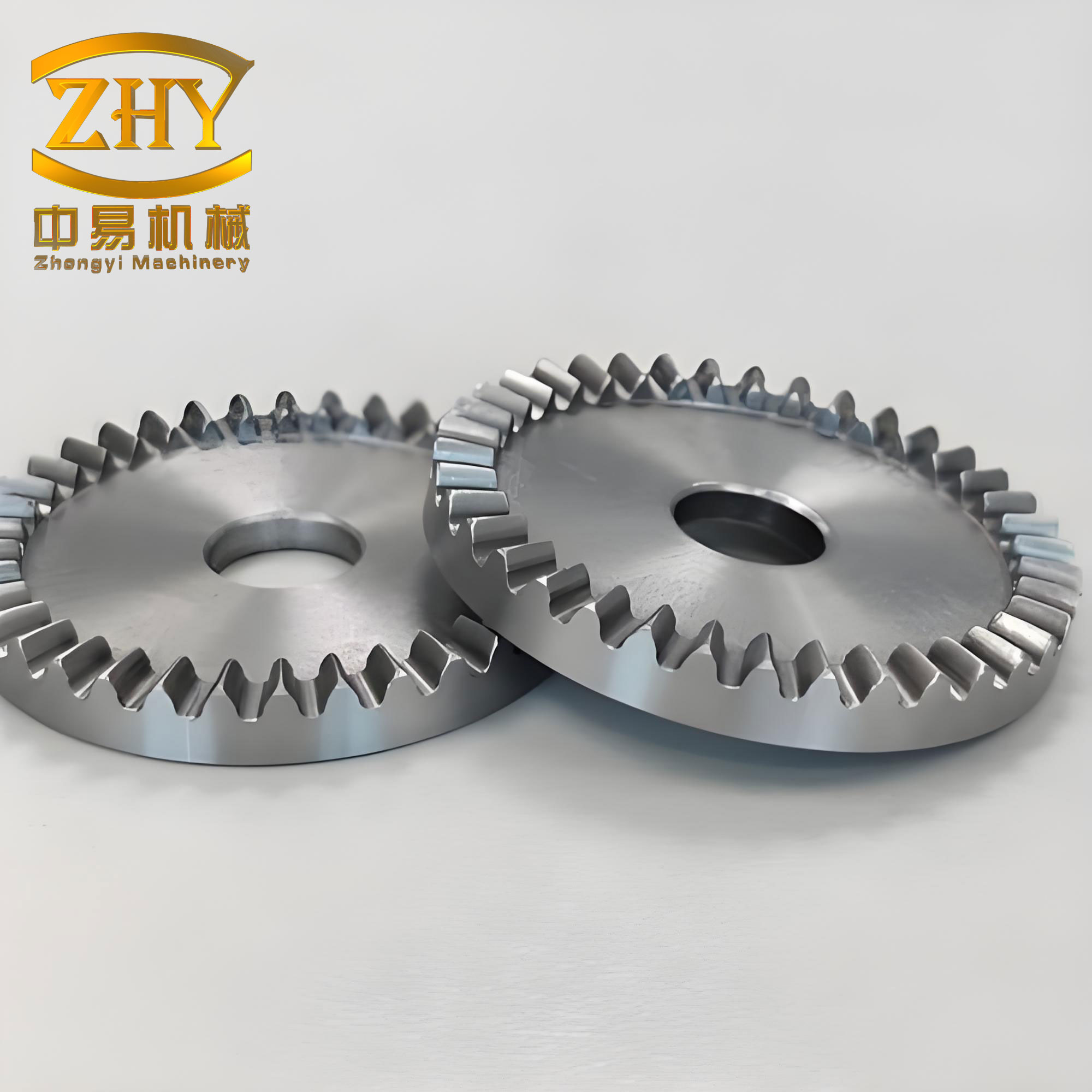
The non-orthogonal asymmetric helical face gear exhibits tooth root undercutting and addendum sharpening. The tooth width decreases from the inner radius to the outer radius. At the minimum inner radius, the tooth root is prone to undercutting because of the small curvature radius. The asymmetric pressure angles cause different undercutting limits on the two sides. At the maximum outer radius, the tooth thickness approaches zero, causing addendum sharpening. These phenomena are illustrated in the accompanying figure.
1.4 Tooth Width Limitations
To avoid undercutting, I eliminate the singular points on the tooth surface. The condition for a singular point is:
$$ v_f = v_p + v_{fp} = 0 $$
where \(v_f\) and \(v_p\) are the velocities of the contact point on the face gear tooth surface and the shaper cutter tooth surface, respectively. \(v_{fp}\) is the relative velocity of the shaper cutter tooth surface with respect to the face gear tooth surface. The coordinate parameter relationship on the undercutting boundary line for the driving side is:
$$ P = \begin{bmatrix} \frac{\partial r_d^f}{\partial e_d} & \frac{\partial r_d^f}{\partial \theta_d} & -v_{fp} \\ \frac{\partial r_d^f}{\partial e_d} & \frac{\partial r_d^f}{\partial \theta_d} & -\frac{\partial f_d^f}{\partial \omega_1}\frac{\partial \omega_1}{\partial t} \end{bmatrix} $$
Solving this with the meshing equation gives the singular point coordinates \((x_{dgq}, y_{dgq}, z_{dgq})\) on the driving side. The radius of the singular point is:
$$ R_{d1} = \sqrt{(x_{dgq})^2 + (y_{dgq})^2} $$
Similarly, for the coast side:
$$ P = \begin{bmatrix} \frac{\partial r_c^f}{\partial e_c} & \frac{\partial r_c^f}{\partial \theta_c} & -v_{fp} \\ \frac{\partial r_c^f}{\partial e_c} & \frac{\partial r_c^f}{\partial \theta_c} & -\frac{\partial f_c^f}{\partial \omega_1}\frac{\partial \omega_1}{\partial t} \end{bmatrix} $$
$$ R_{c1} = \sqrt{(x_{cgq})^2 + (y_{cgq})^2} $$
The minimum inner radius is:
$$ R_1 = \max\{R_{d1}, R_{c1}\} $$
For the addendum sharpening limitation, the tooth width constraint on the driving side is:
$$ \begin{cases} r_d^f(e_d, \theta_d, \omega_1) = M_{p,f} r_d(\theta_d, e_d) \\ f_d^f(e_d, \theta_d, \omega_1) = 0 \end{cases} $$
The coordinates of the point where the addendum thickness is zero on the driving side are \((x_{dbj}, y_{dbj}, z_{dbj})\). The maximum allowable radius is:
$$ R_{d2} = \sqrt{(x_{dbj})^2 + (y_{dbj})^2} $$
On the coast side:
$$ \begin{cases} r_c^f(e_c, \theta_c, \omega_1) = M_{p,f} r_c(\theta_c, e_c) \\ f_c^f(e_c, \theta_c, \omega_1) = 0 \end{cases} $$
$$ R_{c2} = \sqrt{(x_{cbj})^2 + (y_{cbj})^2} $$
The maximum outer radius is:
$$ R_2 = \min\{R_{d2}, R_{c2}\} $$
Therefore, the radius \(R\) of the non-orthogonal asymmetric helical face gear must satisfy:
$$ R_1 < R < R_2 $$
These constraints ensure that the face gear tooth surface is free from undercutting and addendum sharpening, which is essential for reliable operation of the face gear transmission system.
2 Time-Varying Meshing Stiffness Calculation
2.1 Modeling of Time-Varying Meshing Stiffness
The contact ellipse of a face gear is formed by the elastic deformation of the gear teeth. According to Hertz contact theory, when an external load acts on the gear pair, the contact point expands into an elliptical contact area. The center of this contact ellipse is the contact point. I use an improved potential energy method and slice method to calculate the time-varying meshing stiffness of the non-orthogonal asymmetric helical face gear. I divide the gear tooth into trapezoidal slices along the axial direction. The area moment of inertia of the \(i\)-th trapezoidal slice is:
$$ I_i = \frac{h_i^3 (a_i^2 + 4a_i b_i + b_i^2)}{36(a_i + b_i)} $$
where \(h_i\) is the height of the \(i\)-th trapezoidal slice along the tooth profile. \(a_i\) and \(b_i\) are the lengths of the upper and lower bases of the \(i\)-th trapezoidal slice. The bending stiffness \(k_w\) of the face gear tooth is:
$$ k_w = \frac{\int_{y_f}^{y_f+d} \int_{x_{t1}}^{x_{t2}} F \cos\alpha_i \, dx_a dy_a}{N} $$
where \(N\) is the total deflection due to bending and shear of the cantilever beam. The expression for \(N\) is:
$$ N = \sum \left( \frac{F \cos\alpha_i [2h_i^3 + 3h_i^2 (x_{fc} – x_{fp})]}{6EI_i} + \frac{F h_i^2 \cos\alpha_i (x_{fc} – x_{fp})}{2EI_i} + \frac{F^2 h_i (x_{fc} – x_{fp}) \cos\alpha_i (x_{fc} – x_{fp})}{2EI_i} – \frac{h_i^2 y_{fc} \sin\alpha_i}{2EI_i} + \frac{2.4 F h_i \cos\alpha_i}{E h_i (a_i + b_i)} – \frac{y_{fc} \sin\alpha_i 2h_i (x_{fc} – x_{fp})}{2EI_i} \right) \cos\alpha_i $$
where \(y_f\) is the coordinate along the axial direction. \(x_{t1}\) and \(x_{t2}\) are the boundary point coordinates of the elliptical surface load projected onto the plane. \(F\) is the total force on the slice. \(\alpha_i\) is the pressure angle at any point in the contact ellipse. \(x_a\) and \(y_a\) are the horizontal and vertical coordinates of the projection plane. \(x_{fc}\) and \(x_{fp}\) are the normal vector coordinates of the major axis projection point on the projection plane. \(E\) is Young’s modulus. \(y_{fc}\) is the normal vector coordinate of the minor axis projection point on the projection plane. The variables used in the stiffness calculation are summarized in Table 4.
| Symbol | Description |
|---|---|
| \(k_w\) | Bending stiffness of the face gear tooth |
| \(k_b\) | Base coupling stiffness during single tooth meshing |
| \(k_{b1}, k_{b2}\) | Base coupling stiffnesses during double tooth meshing |
| \(k_u\) | Contact stiffness |
| \(k_{m1}\) | Single tooth meshing stiffness |
| \(k_{m2}\) | Double tooth meshing stiffness |
| \(I_i\) | Area moment of inertia of the \(i\)-th trapezoidal slice |
| \(E\) | Young’s modulus |
| \(v\) | Poisson’s ratio |
| \(F\) | Total force on the slice |
| \(\alpha_i\) | Pressure angle at any point in the contact ellipse |
The base coupling stiffness \(k_b\) during single tooth meshing is:
$$ \frac{1}{k_b} = \frac{\cos^2\alpha_i C_1 (V_1 \tan^2\alpha_i + 1)}{I_i E d} + \frac{\cos^2\alpha_i S B_1 L_f (1 – v) + G_1 L_f^2}{S^2 I_i E d} $$
where \(C_1\), \(V_1\), \(B_1\), \(G_1\) are polynomial fitting parameters. \(S\) is the distance from the previous pair of teeth to the next pair of teeth. \(L_f\) is the distance from the contact point to the base. \(v\) is Poisson’s ratio. During double tooth meshing, the base stiffness is:
$$ \frac{1}{k_{b1}} = \frac{\cos\alpha_1 \cos\alpha_2}{I_i E d} \left[ J_2 \tan\alpha_2 + K_2 + \tan\alpha_1 (L_2 \tan^2\alpha_2 + T_2) + \frac{G_2 L_{f1} L_{f2}}{S^2} + (B_2 \tan^2\alpha_1 + C_2) L_{f2} + (V_2 \tan^2\alpha_2 + M_2) \frac{L_{f1}}{S} \right] $$
$$ \frac{1}{k_{b2}} = \frac{\cos\alpha_1 \cos\alpha_2}{I_i E d} \left[ J_3 \tan\alpha_1 + K_3 + \tan\alpha_2 (L_3 \tan^2\alpha_1 + T_3) + \frac{G_3 L_{f1} L_{f2}}{S^2} + (B_3 \tan^2\alpha_2 + C_3) L_{f1} + (V_3 \tan^2\alpha_1 + M_3) \frac{L_{f2}}{S} \right] $$
where \(k_{b1}\) is the base coupling stiffness under the influence of the previous pair of teeth on the next pair. \(k_{b2}\) is the base coupling stiffness under the influence of the next pair of teeth on the previous pair. \(\alpha_1\) and \(\alpha_2\) are the pressure angles of the previous and next teeth. The coefficients \(J_2, K_2, L_2, T_2, G_2, B_2, C_2, V_2, M_2, J_3, K_3, L_3, T_3, G_3, B_3, C_3, V_3, M_3\) are polynomial fitting coefficients. \(L_{f1}\) and \(L_{f2}\) are the distances from the contact points of the previous and next teeth to the base. The polynomial fitting parameters are listed in Table 5.
| Parameter | Value | Parameter | Value |
|---|---|---|---|
| \(C_1\) | 0.12 | \(V_1\) | 0.08 |
| \(B_1\) | 0.15 | \(G_1\) | 0.05 |
| \(J_2\) | 0.22 | \(K_2\) | 0.18 |
| \(L_2\) | 0.11 | \(T_2\) | 0.09 |
| \(G_2\) | 0.07 | \(B_2\) | 0.13 |
| \(C_2\) | 0.06 | \(V_2\) | 0.04 |
| \(M_2\) | 0.03 | \(J_3\) | 0.21 |
| \(K_3\) | 0.17 | \(L_3\) | 0.10 |
| \(T_3\) | 0.08 | \(G_3\) | 0.06 |
| \(B_3\) | 0.12 | \(C_3\) | 0.05 |
| \(V_3\) | 0.03 | \(M_3\) | 0.02 |
According to Hertz contact theory, the contact stiffness \(k_u\) is:
$$ \frac{1}{k_u} = \frac{1.37}{F^{0.1} E^{0.9} d^{0.8}} $$
The single tooth meshing stiffness is:
$$ k_{m1} = \frac{1}{\frac{1}{k_w} + \frac{1}{k_b} + \frac{1}{k_u}} $$
The double tooth meshing stiffness is:
$$ k_{m2} = \frac{1}{\frac{1}{k_w} + \frac{1}{k_{b1}} + \frac{1}{k_{b2}} + \frac{1}{k_u}} $$
2.2 Influence of Pressure Angle on Time-Varying Meshing Stiffness
I fix the shaft angle at 60° and vary the pressure angle from 15° to 30°. The contact trace shifts toward the outer radius, and the contact area expands. The time-varying meshing stiffness increases with pressure angle. Table 6 shows the calculated average meshing stiffness for different pressure angles.
| Pressure angle \(\alpha\) (°) | Average meshing stiffness (N·mm⁻¹) × 10⁴ | Contact trace position |
|---|---|---|
| 15 | 4.2 | Inner region |
| 20 | 4.8 | Middle region |
| 25 | 5.5 | Outer-middle region |
| 30 | 6.3 | Outer region |
The increase in pressure angle enlarges the contact area and improves the load distribution, leading to higher meshing stiffness. This helps improve the efficiency and reliability of the face gear transmission system. The contact trace movement and stiffness variation confirm that increasing the pressure angle from 15° to 30° significantly enhances the time-varying meshing stiffness of the non-orthogonal asymmetric helical face gear.
2.3 Influence of Shaft Angle on Time-Varying Meshing Stiffness
I fix the pressure angle at 20° and vary the shaft angle from 30° to 90°. The contact trace shifts toward the inner radius as the shaft angle increases. The time-varying meshing stiffness decreases with increasing shaft angle. Table 7 shows the results.
| Shaft angle \(\gamma\) (°) | Average meshing stiffness (N·mm⁻¹) × 10⁴ | Contact trace position |
|---|---|---|
| 30 | 6.5 | Outer region |
| 45 | 5.8 | Middle-outer region |
| 60 | 4.9 | Middle region |
| 90 | 4.1 | Inner region |
A smaller shaft angle moves the contact trace toward the outer radius, increasing the meshing stiffness. Therefore, reducing the shaft angle from 90° to 30° can significantly improve the time-varying meshing stiffness of the non-orthogonal asymmetric helical face gear. This characteristic is helpful for optimizing the reliability of the face gear transmission system.
3 Finite Element Verification
I use finite element simulation to verify the calculated time-varying meshing stiffness. I import the tooth surface point cloud generated from the meshing equations into modeling software to build a three-dimensional model of the non-orthogonal asymmetric helical face gear. I then mesh the gear pair and import it into finite element analysis software. I define elastic material parameters and friction coefficients. I select the non-orthogonal asymmetric helical cylindrical gear as the driving wheel and couple the mesh model to a reference point for kinematic simulation. I release the rotational degree of freedom along the end face axis so that the tooth surfaces are in contact. In the post-processing module, I monitor the gear rotation angle and output the meshing force. I process the data to obtain the time-varying meshing stiffness from the finite element simulation. I compare the simulated stiffness with the theoretical calculated value to verify the accuracy of the finite element model and the rationality of the settings.
Table 8 shows the comparison between calculated and simulated time-varying meshing stiffness for different pressure angles at a fixed shaft angle of 60°.
| Pressure angle \(\alpha\) (°) | Calculated average stiffness (N·mm⁻¹) × 10⁴ | Simulated average stiffness (N·mm⁻¹) × 10⁴ | Error (%) |
|---|---|---|---|
| 15 | 4.20 | 4.41 | 4.95 |
| 20 | 4.80 | 4.99 | 3.99 |
| 25 | 5.50 | 5.72 | 4.03 |
| 30 | 6.30 | 6.54 | 3.85 |
Table 9 shows the comparison for different shaft angles at a fixed pressure angle of 20°.
| Shaft angle \(\gamma\) (°) | Calculated average stiffness (N·mm⁻¹) × 10⁴ | Simulated average stiffness (N·mm⁻¹) × 10⁴ | Error (%) |
|---|---|---|---|
| 30 | 6.50 | 6.58 | 1.28 |
| 45 | 5.80 | 5.97 | 2.90 |
| 60 | 4.90 | 5.07 | 3.40 |
| 90 | 4.10 | 4.16 | 1.48 |
The errors between the calculated and simulated values are all within 5%, indicating that my calculation model is reliable and accurate. The comparison also reveals the contact characteristics of the face gear, which provides an important theoretical basis for design optimization and performance improvement of face gear transmission systems.
3.1 Mesh Convergence Study
To ensure the accuracy of the finite element simulation, I performed a mesh convergence study. I varied the number of elements on the tooth surface and monitored the maximum contact stress and the time-varying meshing stiffness. The results are shown in Table 10. Based on this study, I selected a mesh size that provides a good balance between accuracy and computational efficiency.
| Mesh size (mm) | Number of elements | Maximum contact stress (MPa) | Average meshing stiffness (N·mm⁻¹) × 10⁴ |
|---|---|---|---|
| 0.50 | 125,000 | 845 | 4.92 |
| 0.40 | 198,000 | 852 | 4.95 |
| 0.30 | 342,000 | 856 | 4.97 |
| 0.25 | 512,000 | 857 | 4.98 |
The results show that the mesh size of 0.30 mm provides sufficient accuracy, as the variation in meshing stiffness is less than 1% compared with the finer mesh.
4 Conclusion
I have calculated and analyzed the time-varying meshing stiffness of non-orthogonal asymmetric helical face gears under different pressure angles and shaft angles using the slice method and potential energy method. I verified the results with finite element simulation. The calculated values are consistent with the simulation results, and the errors are all within 5%, which verifies the effectiveness and accuracy of my calculation method.
When the shaft angle is fixed at 60°, the time-varying meshing stiffness of the non-orthogonal asymmetric helical face gear increases significantly as the pressure angle increases from 15° to 30°. The contact trace shifts toward the outer radius. Increasing the pressure angle helps improve the stability of the face gear transmission system.
When the pressure angle is fixed at 20°, the time-varying meshing stiffness decreases as the shaft angle increases from 30° to 90°. The contact trace shifts toward the inner radius. Reducing the shaft angle has a positive effect on improving the performance of the non-orthogonal asymmetric helical face gear transmission system.
Therefore, increasing the pressure angle from 15° to 30° or reducing the shaft angle from 90° to 30° can significantly improve the time-varying meshing stiffness of non-orthogonal asymmetric helical face gears. This provides important theoretical support for the design and application of face gears. I also note that the tooth width limitations, including undercutting and addendum sharpening, must be carefully considered. The minimum inner radius and maximum outer radius are determined by the singular points and zero thickness points. The radius must satisfy the condition \(R_1 < R < R_2\).
In summary, my study provides a comprehensive method for designing non-orthogonal asymmetric helical face gears and calculating their time-varying meshing stiffness. The results can guide the optimization of face gear transmission systems for high-precision applications. The improved potential energy method combined with the slice method is effective for analyzing the meshing characteristics of non-orthogonal asymmetric helical face gears. Future work can extend this method to consider more complex operating conditions, such as misalignment, friction, and dynamic loads, to further enhance the reliability and performance of face gear transmission systems.
The face gear design approach presented here can be used to generate accurate tooth surface models for various shaft angles and pressure angle combinations. The meshing stiffness calculation method can be integrated into dynamic models of face gear transmission systems to predict vibration and noise. The finite element verification provides confidence in the theoretical predictions. Overall, this research contributes to the advancement of non-orthogonal asymmetric helical face gear technology and supports the development of high-performance gear transmission systems for aviation and other demanding applications.