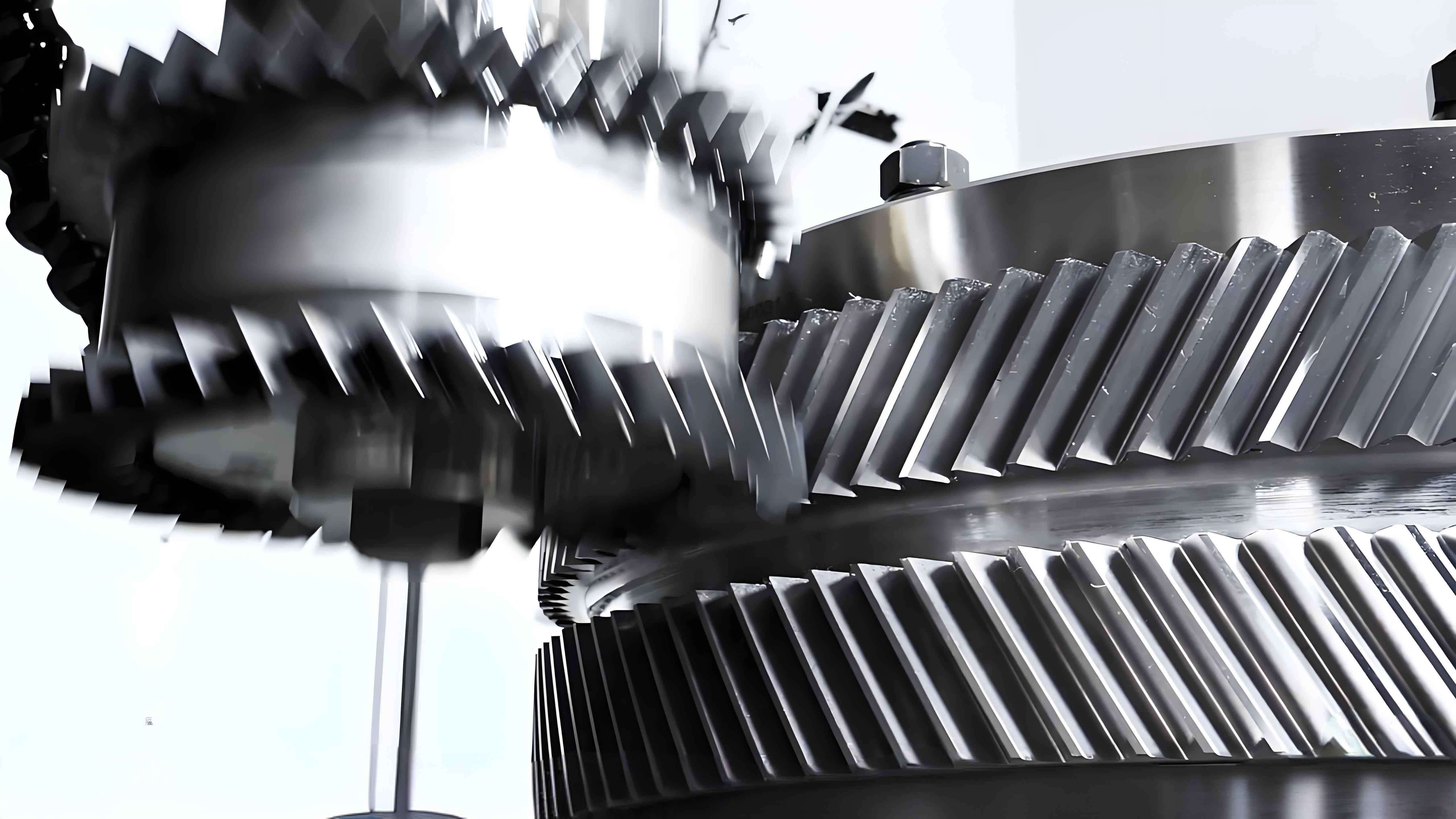
Herringbone gears exhibit superior load-bearing capacity, high contact ratio, and operational reliability, making them ideal for high-speed and heavy-load applications. This study investigates the nonlinear dynamic characteristics of herringbone gear transmission systems under extreme operating conditions, providing critical insights for stability optimization.

1. Dynamic Modeling of Herringbone Gear System
The 24-degree-of-freedom nonlinear dynamic model incorporates time-varying meshing stiffness, backlash, bearing clearance, and transmission errors. Key parameters for the herringbone gear system are summarized in Table 1.
| Parameter | Input Gear | Output Gear |
|---|---|---|
| Number of Teeth | 22 | 41 |
| Module (mm) | 5 | 5 |
| Helix Angle (°) | 22 | 22 |
The dimensionless dynamic equations are expressed as:
$$ \bar{x}_{n1} = (\bar{x}_1-\bar{x}_2)\sin\alpha_n + (\bar{y}_1-\bar{y}_2)\cos\alpha_n\cos\beta – \kappa_{m1}f(\bar{x}_{n1}) – \xi_{m1}\dot{\bar{x}}_{n1} + f_1 + f_{e1} $$
$$ \bar{x}_{n2} = (\bar{x}_3-\bar{x}_4)\sin\alpha_n + (\bar{y}_3-\bar{y}_4)\cos\alpha_n\cos\beta – \kappa_{m2}f(\bar{x}_{n2}) – \xi_{m2}\dot{\bar{x}}_{n2} + f_1 + f_{e2} $$
2. Time-Varying Excitation Mechanisms
The time-varying meshing stiffness for herringbone gears follows:
$$ K(t) = K_m + K_i\cos(\omega_m t + \phi_0) $$
$$ K_i = \frac{\sqrt{2-2\cos[2\pi i(\varepsilon_\alpha-1)]}}{\pi i}K_c $$
Bearing forces considering clearance effects are calculated using:
$$ F_{bx} = \sum_{i=1}^{Z_b} K_b\delta^n\cos\gamma’_i H(\delta)\cos\theta_i $$
$$ F_{by} = \sum_{i=1}^{Z_b} K_b\delta^n\cos\gamma’_i H(\delta)\sin\theta_i $$
3. Nonlinear Dynamic Response Analysis
The 4th-order Runge-Kutta method reveals significant parametric influences:
| Parameter | Stability Trend | Critical Range |
|---|---|---|
| Input Torque | Negative | 150-300 N·m |
| Damping Ratio | Positive | 0.15-0.30 |
| Backlash | Negative | 1-4 μm |
Bifurcation analysis demonstrates the system’s state transitions:
$$ \text{Lyapunov Exponent} = \begin{cases}
<0 & \text{Periodic Motion} \\
\geq0 & \text{Chaotic Motion}
\end{cases} $$
4. Frequency Domain Characteristics
Wavelet transforms reveal distinct frequency components:
$$ \text{Instantaneous Frequency} = \frac{1}{2\pi}\frac{d}{dt}\arg[x(t) + j\mathcal{H}\{x(t)\}] $$
where $\mathcal{H}$ denotes Hilbert transform. Frequency bifurcation occurs at critical excitation frequencies:
$$ \omega_{cr} = \sqrt{\frac{K_m}{m_e}} \pm \Delta\omega $$
5. Stability Optimization Strategies
Key recommendations for herringbone gear system design:
- Maintain input torque below 250 N·m
- Optimize damping ratio >0.25
- Control backlash within 2-3 μm
- Avoid excitation frequencies in 1.2-1.7ω_n range
This comprehensive analysis establishes a theoretical foundation for enhancing the operational stability of high-speed heavy-load herringbone gear transmissions, particularly in aerospace and energy transmission applications.
