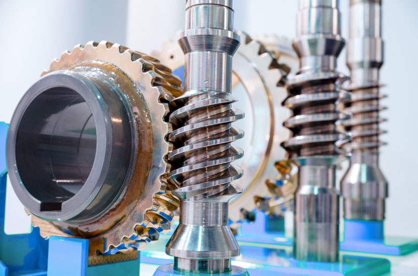
Worm gear transmission systems are widely used in aerospace, autonomous vehicles, and smart home applications due to their compact structure, high transmission efficiency, and self-locking properties. This study establishes a nonlinear dynamic model considering time-varying meshing stiffness, backlash, and comprehensive transmission errors to analyze the dynamic characteristics of worm gear systems under different operating conditions.
1. Dynamic Modeling
The lumped parameter method is employed to establish a three-dimensional coupled bending-torsional-axial dynamic model for worm gear systems. The dimensionless governing equations are derived as:
$$
\begin{cases}
\ddot{x}_1 + 2\xi_{1x}\dot{x}_1 + k_{1x}f(x_1) + a_1k_pf(x_n) = 0 \\
\ddot{y}_1 + 2\xi_{1y}\dot{y}_1 + k_{1y}f(y_1) + a_2k_pf(x_n) = 0 \\
\ddot{z}_1 + 2\xi_{1z}\dot{z}_1 + k_{1z}f(z_1) – a_3k_pf(x_n) = 0 \\
\ddot{x}_2 + 2\xi_{2x}\dot{x}_2 + k_{2x}f(x_2) – a_1k_pf(x_n) = 0 \\
\ddot{y}_2 + 2\xi_{2y}\dot{y}_2 + k_{2y}f(y_2) – a_2k_pf(x_n) = 0 \\
\ddot{z}_2 + 2\xi_{2z}\dot{z}_2 + k_{2z}f(z_2) + a_3k_pf(x_n) = 0 \\
\ddot{\theta}_1 + 2\xi_{g}\dot{\theta}_1 = T_g – F_nR_1 \\
\ddot{\theta}_2 + 2\xi_{e}\dot{\theta}_2 = T_e – F_nR_2
\end{cases}
$$
Where the nonlinear backlash function is defined as:
$$
f(X) =
\begin{cases}
X – B, & X > B \\
0, & |X| \leq B \\
X + B, & X < -B
\end{cases}
$$
The equivalent meshing displacement considering transmission errors is:
$$
x_n = a_1(x_1 – x_2) + a_2(y_1 – y_2) – a_3(z_1 – z_2) – e_m\cos(\omega t + \phi)
$$
| Parameter | Value |
|---|---|
| Normal modulus (mm) | 4 |
| Worm thread count | 3 |
| Worm diameter (mm) | 44 |
| Gear ratio | 12.33 |
| Backlash (μm) | 100 |
| Meshing stiffness (N/m) | 2×10⁹ |
2. Nonlinear Dynamics Analysis
The 4th-order variable-step Runge-Kutta method is adopted for numerical simulation. Bifurcation diagrams, phase trajectories, and Poincaré maps reveal complex dynamic behaviors:
2.1 Meshing Frequency Effects
Figure 2 demonstrates the system’s response under varying dimensionless meshing frequencies ω ∈ [0.1, 2.5]:
- Period-1 motion dominates at ω < 0.5089 with full engagement
- Grazing bifurcation occurs at ω = 0.5089
- Period-doubling cascades lead to chaos at ω > 1.3
- Stable period-1 motion recovers at ω ≥ 1.7195
2.2 Damping Ratio Effects
Increasing meshing damping ratio ξ significantly suppresses chaotic behavior:
| Damping Ratio | Dynamic Response |
|---|---|
| ξ = 0.08 | Chaos in ω ∈ [1.35, 1.6] |
| ξ = 1.0 | Period-4 motion |
| ξ = 1.2 | Stable period-1 motion |
The dimensionless damping force is expressed as:
$$
F_d = 2\xi\sqrt{k_p m}\dot{x}_n
$$
3. Design Implications
Critical findings for worm gear system optimization:
- Chaotic regions should be avoided through proper frequency selection
- Optimal damping ratio range: ξ ∈ [1.0, 1.2]
- Backlash control is crucial for low-frequency stability
- Stiffness modulation reduces impact vibrations
This analysis provides theoretical guidance for enhancing the stability and reliability of worm gear transmissions in precision mechanical systems. The proposed methodology enables effective dynamic parameter selection during worm gear design phases.
