The research object of the model is a two-stage planetary gear system, and the system diagram is shown in Figure 1. It consists of two-stage 2K-H Planetary Gear Trains in series. The input end is the first stage planet carrier C Ⅰ, and the output end is the second stage sun gear s Ⅱ. The two-stage inner gear rings R Ⅰ and R Ⅱ are fixed components. S Ⅰ and C Ⅱ are the same components, expressed by a, P Ⅰ I and P Ⅱ I (I = 1 , N, n are the number of planetary gears) respectively represent the first stage and the second stage planetary gears.
The lumped parameter method is used to establish the system dynamics model, and the following assumptions are made
① Assuming that each gear is a rigid body, the meshing gear is simplified as a cylinder connected by a spring, and the stiffness coefficient of the spring is the meshing stiffness of the meshing gear;
② Assuming that the torsional stiffness of the planet carrier is large and the torsional flexibility of the planet carrier is ignored, the first stage sun gear and the second stage planet carrier can be considered as one component;
③ The parameters of N groups of planetary gears are identical;
④ The influence of friction between gear teeth and bearing on operation is not considered.
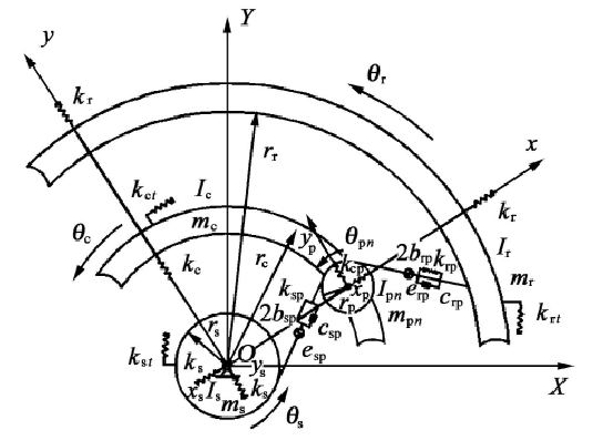
The stiffness of the transmission shaft and bearing of the system is not large enough, that is, the translational vibration of the gear can not be ignored. Taking the first stage as an example, its “translation torsion” coupling dynamic model is shown in Figure 2. Where, s, C, R and P represent the sun gear, planet carrier, inner ring gear and planet gear respectively, oxy is the fixed coordinate system and oxy is the moving coordinate system, oxy rotates relative to oxy at the angular velocity of the planet gear. Each component shown in Fig. 2 has three degrees of freedom. Xi and Yi (I = s, C, R, PN) represent the translational displacement of the component in X and Y directions, and θ I represents the rotation angle of the component. MI and II represent the mass and moment of inertia of each component respectively; RI represents the radius of base circle; Ki and kit represent the radial support stiffness and tangential stiffness of components respectively; kJ, 2BJ, CJ and EJ (J = s Ⅰ P Ⅰ n, R Ⅰ P Ⅰ n) represent the meshing stiffness, backlash, meshing damping and meshing error of each gear pair respectively.


