
The rotary vector reducer, a precision speed reduction mechanism, is a cornerstone of modern robotic joints, particularly in heavy-duty applications such as industrial robot bases and arms. Its dynamic performance—encompassing vibration, transmission error, and torsional stiffness—directly dictates the positioning accuracy, stability, and service life of the entire robotic system. Therefore, establishing an accurate and computationally tractable dynamic model is paramount for understanding its behavior, diagnosing potential issues, and guiding its design optimization. This work focuses on developing a simplified yet effective pure torsional dynamic model to capture the essential nonlinear characteristics of a rotary vector reducer during operation.
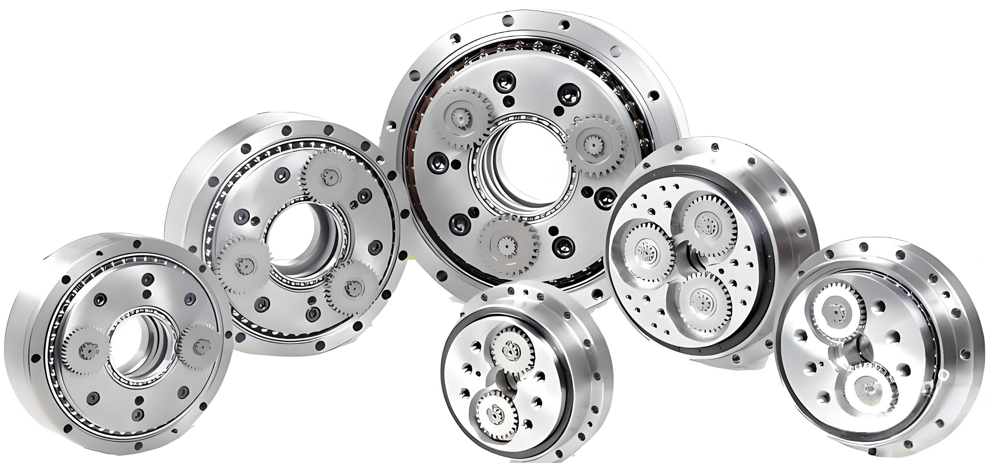
The structure of a two-stage rotary vector reducer is central to its function. The system comprises several key subsystems interacting through various compliance elements. The first stage is a planetary gear train consisting of a sun gear, two planet gears, and a carrier (which is also the output member). The second, and defining, stage is a cycloidal-pin gear mechanism. Each planet gear is rigidly connected to a crankshaft. The crankshafts drive two cycloidal gears, which then mesh with a stationary ring of pins (the pin gear). The interaction between the cycloidal gears and the pin gear forces the carrier to rotate at a greatly reduced speed. The overall reduction ratio, typically very high (e.g., 1:105), results from the combined effect of the first-stage planetary differential and the second-stage cycloidal motion.
1. A 5-Degree-of-Freedom Pure Torsional Model
To analyze the system’s dynamics, we construct a lumped-parameter model. Each major rotating component is represented by a concentrated mass with inertia, and the connections between them are modeled as springs and dampers. This approach simplifies the complex three-dimensional geometry into a one-dimensional torsional vibration system, focusing on the primary dynamic effects.
1.1 Model Assumptions and Subsystems
To make the problem tractable, several simplifying assumptions are made:
- The analysis focuses on internal nonlinearities; external fluctuations in input speed and load torque are not considered.
- Gear meshing is ideal, meaning the line of action is fixed, and friction at gear contacts is neglected.
- Axial forces and deformations, as well as bending of the crankshafts, are not considered. Only rotational motion in the plane perpendicular to the axis is analyzed.
- The torsional and bending stiffnesses of the crankshafts are considered high enough to treat each planet-crankshaft assembly as a single rigid body with a combined moment of inertia.
Based on these assumptions, the rotary vector reducer system is decomposed into five dynamic subsystems, leading to a 5-degree-of-freedom (DOF) model. The generalized coordinates are the rotational angles of these subsystems: the input shaft ($\theta_0$), the sun gear ($\theta_1$), the two planet-crankshaft assemblies ($\theta_{2i}$, where $i=0,1$), the two cycloidal gears ($\theta_{3j}$, where $j=0,1$), and the carrier ($\theta_5$).
| Subsystem | Components Represented | Generalized Coordinate | Degree of Freedom |
|---|---|---|---|
| 1. Input Shaft | Motor rotor, input shaft segment | $\theta_0$ | 1 |
| 2. Sun Gear | Sun gear | $\theta_1$ | 1 |
| 3. Planet-Crankshaft | Planet gear and its connected crankshaft (2 assemblies) | $\theta_{2i}$ | 2 |
| 4. Cycloidal Gear | Cycloidal gear (2 gears) | $\theta_{3j}$ | 2 |
| 5. Carrier | Output carrier (planetary carrier) | $\theta_5$ | 1 |
Total Degrees of Freedom: 7 (considering two planet and two cycloidal gears) are reduced to 5 primary dynamic coordinates in the modeling approach.
1.2 Derivation of Dynamic Equations
The equations of motion are derived using D’Alembert’s principle (torque balance) for each subsystem. The model incorporates several key compliance elements: input shaft torsional stiffness, gear mesh stiffnesses, and bearing support stiffnesses at the crank-cycloid and crank-carrier interfaces. Damping is included for each compliant connection.
1.2.1 Input Shaft:
The torque balance for the input shaft subsystem, considering the motor torque $T_M$, input shaft stiffness $k_{01}$, and damping $c_{01}$, is:
$$J_0 \ddot{\theta}_0 = T_M – k_{01}(\theta_0 – \theta_1) – c_{01}(\dot{\theta}_0 – \dot{\theta}_1)$$
where $J_0$ is the inertia of the input shaft and attached motor components.
1.2.2 Sun Gear:
The sun gear is driven by the input shaft and meshes with the two planet gears. The relative displacement at each sun-planet mesh is $x_{12i} = r_1 \theta_1 – r_2 \theta_{2i}$, where $r_1$ and $r_2$ are the base circle radii. The dynamic meshing force $F_{12i}$ includes stiffness $k_{12}$, damping $c_{12}$, and transmission error excitation $\zeta_{12i}(t)$.
$$F_{12i} = k_{12} (x_{12i} – \zeta_{12i}) + c_{12} (\dot{x}_{12i} – \dot{\zeta}_{12i})$$
The equation of motion is:
$$J_1 \ddot{\theta}_1 = k_{01}(\theta_0 – \theta_1) + c_{01}(\dot{\theta}_0 – \dot{\theta}_1) – \sum_{i=0}^{1} r_1 F_{12i}$$
where $J_1$ is the sun gear’s inertia.
1.2.3 Planet-Crankshaft Assembly:
This assembly is acted upon by the sun-planet mesh force and the forces from the two cycloidal gears mounted on its crank pins. The forces at the crank pin ($F_{3j4iY}, F_{3j4iX}$) depend on the relative deflection between the crank pin and the cycloidal gear’s center, which is a function of the crank’s rotation ($\theta_c = \theta_0 / N_1$, with $N_1$ as the first-stage ratio) and the eccentricity $e_c$. The equations involve projections of these forces to create a torque.
$$J_2 \ddot{\theta}_{2i} = r_2 F_{12i} – [ (F_{3(0)4iY} – F_{3(1)4iY}) e_c \sin \theta_c + (F_{3(0)4iX} – F_{3(1)4iX}) e_c \cos \theta_c ]$$
where $J_2$ is the combined inertia of the planet gear and crankshaft.
1.2.4 Cycloidal Gear:
Each cycloidal gear experiences forces from its meshing with the fixed pin gear ($F_{63j}$) and from the two crank pins of the planet-crankshaft assemblies ($F_{3j4iY}, F_{3j4iX}$). The pin mesh force is a function of the effective mesh stiffness $k_{36}$, damping $c_{36}$, and the kinematic motion of the cycloid relative to the pins.
$$J_3 \ddot{\theta}_{3j} = F_{63j} r_c’ \cos \alpha_c + a_0 [ (F_{3j4(1)Y} – F_{3j4(0)Y}) \sin \theta_g + (F_{3j4(0)X} – F_{3j4(1)X}) \cos \theta_g ]$$
Here, $J_3$ is the cycloidal gear’s inertia, $r_c’$ is the generating radius, $\alpha_c$ is the pressure angle, $a_0$ is half the distance between crank centers, and $\theta_g = \theta_0 / N_{total}$ is the theoretical carrier rotation angle ($N_{total}$ is the total reduction ratio, e.g., 105).
1.2.5 Carrier (Output):
The carrier is loaded by the output torque $T_L$ and is connected to the crankshafts via support bearings. Forces at these bearing connections ($F_{54iY}, F_{54iX}$) create the output torque.
$$J_5 \ddot{\theta}_5 = a_0 \sum_{i=0}^{1} [ -F_{54iX} \cos(\theta_g + \pi i) + F_{54iY} \sin(\theta_g + \pi i) ] – T_L$$
where $J_5$ is the carrier’s inertia.
The complete system is thus described by a set of five coupled, second-order, nonlinear differential equations with time-varying coefficients (due to the periodic nature of gear meshing and rotating coordinate transformations).
2. Solution of the Dynamic Equations
The derived system of equations is semi-definite and contains rigid-body motion. To eliminate this and facilitate numerical solution, a coordinate transformation is performed. New generalized coordinates are defined as relative displacements between components, such as the torsional deflection of the input shaft ($x_{01} = \theta_0 – \theta_1$) and the linear displacement along the line of action for the sun-planet mesh ($x_{12i}$). This transformation yields 11 equations for the 11 relative coordinates. These equations are then normalized (non-dimensionalized) to improve numerical stability and solved using a time-discrete numerical integration method, such as the fourth-order Runge-Kutta method.
2.1 Parameter Calculation
Accurate dynamic simulation requires precise calculation of system parameters. Key parameters for a specific rotary vector reducer design (e.g., RV-40E type) are summarized below.
| Parameter | Symbol | Value | Unit |
|---|---|---|---|
| Input Stage | |||
| Sun-Planet Mesh Stiffness | $k_{12}$ | $1.648 \times 10^8$ | N/m |
| Sun-Planet Mesh Damping | $c_{12}$ | $0.0214$ | N·s/m |
| Input Shaft Torsional Stiffness | $k_{01}$ | $7.677 \times 10^4$ | N·m/rad |
| Input Shaft Inertia | $J_0$ | $73.18 \times 10^{-6}$ | kg·m² |
| Sun Gear Inertia | $J_1$ | $2.794 \times 10^{-6}$ | kg·m² |
| Planet-Crankshaft Inertia | $J_2$ | $56.64 \times 10^{-6}$ | kg·m² |
| Cycloid Stage | |||
| Cycloid-Pin Mesh Stiffness | $k_{36}$ | $1.511 \times 10^7$ | N·m/rad |
| Cycloid-Pin Mesh Damping | $c_{36}$ | $4.899 \times 10^{-4}$ | N·s·m/rad |
| Crank-Cycloid Bearing Stiffness | $k_{34}$ | $3.717 \times 10^8$ | N/m |
| Crank-Carrier Bearing Stiffness | $k_{54}$ | $3.315 \times 10^8$ | N/m |
| Cycloidal Gear Inertia | $J_3$ | $723.3 \times 10^{-6}$ | kg·m² |
| Carrier Inertia | $J_5$ | $896.7 \times 10^{-6}$ | kg·m² |
*Note: Stiffnesses are highly dependent on design geometry and bearing selection.
2.2 Dynamic Response During Start-up and Steady State
The model is simulated for a start-up condition where the input torque follows a simplified motor characteristic curve until a target speed (e.g., 10 rpm) is reached, after which speed is held constant under a 30 N·m load. The results confirm the model’s validity: the steady-state angular displacement ratio between input ($\theta_0$) and output ($\theta_5$) converges to exactly 105, matching the design reduction ratio of the modeled rotary vector reducer. Key dynamic responses include:
- Torsional Deflections: The relative twist of the input shaft ($x_{01}$) and the sun-planet mesh displacement ($x_{12}$) show significant transient oscillation during start-up but quickly dampen to a small, steady-state value, indicating stable engagement of the first stage.
- Transmission Error: The overall transmission error, defined as the difference between the actual and theoretical carrier position ($\Delta \theta_5 = \theta_5 – \theta_0 / 105$), stabilizes to a periodic waveform with a very small amplitude. Theoretical analysis shows this error remains below 0.3 arc-minutes (< 8.73e-5 rad), which meets the high-precision requirement for rotary vector reducers (typically < 1 arc-minute).
- Frequency Spectrum: The Fourier transform of the steady-state transmission error reveals a dominant frequency component. For an input speed of 10 rpm (0.1667 Hz), the primary meshing frequency and its relationship to the reduction ratio dictate this dominant frequency, confirming the system operates in a periodic, stable state.
3. Influence of Nonlinear Factors on Dynamic Characteristics
The linear model provides a baseline. In reality, several nonlinear factors significantly impact the dynamic behavior of a rotary vector reducer. These factors are incorporated into the model to assess their individual effects.
| Transmission Stage | Nonlinear Factor | Physical Cause | Model Representation |
|---|---|---|---|
| First Stage (Spur Gears) | Time-Varying Mesh Stiffness (TVMS) | Changing number of teeth in contact during mesh cycle. | $k_{12}(t) = \bar{k}_{12} + \Delta k_{12}(t)$, where $\Delta k_{12}(t)$ is periodic. |
| Mesh Error & Profile Deviation | Manufacturing inaccuracies, installation errors. | Kinematic excitation $\zeta_{12}(t)$ added to mesh displacement. | |
| Backlash (Clearance) | Necessary gap between teeth to prevent jamming. | Piecewise linear force-displacement relationship: $F=0$ within the clearance zone $\eta$. | |
| Second Stage (Cycloid-Pin) | Time-Varying Mesh Stiffness | Changing number of cycloid teeth in contact with pins; affected by clearance. | $k’_{36}(t) = \bar{k}’_{36} + \Delta k’_{36}(t)$. |
| Mesh Error | Cycloid profile errors, pin position errors. | Excitation $\zeta_{36}(t)$ in the cycloid-pin mesh equation. | |
| Nonlinear Clearance Distribution | Differing initial clearances for each pin due to manufacturing tolerances. | Affects which pins are in contact, thereby modifying the effective $k’_{36}(t)$. |
3.1 Impact of First-Stage Nonlinearities:
Simulations isolating these effects reveal distinct influences:
- TVMS: Reduces the amplitude of transient vibrations during start-up and slightly decreases the steady-state sun-planet mesh transmission error. It acts as a stabilizing factor for the first stage.
- Mesh Error: Significantly increases the amplitude of oscillations in the first-stage mesh error ($x_{12}$) and has a noticeable, though smaller, amplifying effect on the overall system transmission error ($\Delta \theta_5$). It is a primary source of vibration excitation.
- Backlash: Can reduce the input shaft torsional vibration but leads to increased impacts at the gear teeth, manifesting as higher amplitudes in the first-stage mesh error. Its effect on the final output error is mixed but generally slightly detrimental.
3.2 Impact of Second-Stage Nonlinearities:
The cycloid-pin mesh dynamics are crucial for the rotary vector reducer’s precision.
- TVMS (Cycloid): Notably reduces the vibration amplitude of the cycloidal gear itself ($\Delta \theta_3$), contributing to smoother operation of the core speed reduction stage.
- Mesh Error (Cycloid): Has the most pronounced negative effect on the cycloid stage, causing large increases in the cycloidal gear’s vibration. This directly threatens the positioning accuracy of the system.
- Clearance: Its main effect is to slightly reduce the effective mesh stiffness, which can modestly increase vibration but is less critical than mesh errors.
Overall Conclusion on Nonlinearities: While the rotary vector reducer demonstrates inherent stability, the analysis highlights that gear mesh errors—particularly in the cycloid stage—are the most critical nonlinear factors to control during manufacturing and assembly to ensure low vibration and high precision. Time-varying stiffness generally has a damping effect, while backlash requires careful design optimization.
4. Experimental Validation
To validate the theoretical model, a comprehensive dynamic performance test platform for rotary vector reducers was constructed. This platform can measure multiple parameters including torque, speed, efficiency, and critically, transmission error and vibration spectrum.
4.1 Test Platform and Procedure:
The platform consists of a drive motor, input torque/speed sensor, the rotary vector reducer under test (RV-40E type), an output torque/speed sensor, a gearbox for loading, and a load motor. High-resolution angular encoders are mounted on both the input and output shafts to measure transmission error. The test was conducted under conditions matching the simulation: input speed accelerated and held at 10 rpm, with a load torque maintained at approximately 30 N·m.
4.2 Comparison of Theoretical and Experimental Results:
- Transmission Error Magnitude: The experimentally measured peak-to-peak transmission error over two output revolutions was between 50″ and 54″ (arc-seconds). This is reasonably close to the theoretical model’s prediction of approximately 18″-26″ (depending on included nonlinearities). The slightly higher experimental value is expected due to unmodeled real-world factors such as component imperfections, bearing nonlinearities, and measurement noise.
- Frequency Spectrum: The experimental frequency spectrum of the transmission error showed multiple peaks. The most prominent peak occurred at approximately 0.1057 Hz. This aligns very closely with the dominant frequency of 0.1035 Hz predicted by the theoretical model for the 10 rpm input condition. The presence of additional spectral lines in the experiment is attributed to other sources of excitation in the physical system not captured in the simplified 5-DOF model, such as electromagnetic ripple from motors or subtle asymmetries.
This agreement between the theoretical and experimental results in both the time-domain (error magnitude) and frequency-domain (dominant frequency) validates the correctness of the established 5-DOF pure torsional model for the rotary vector reducer. It confirms that the model captures the essential dynamics governing transmission error and system stability.
5. Conclusion
This work successfully developed and analyzed a 5-degree-of-freedom pure torsional dynamic model for a rotary vector reducer. The model, based on lumped parameters and D’Alembert’s principle, effectively simplifies the complex multi-body system into a solvable set of equations. Key achievements include:
- The model correctly predicts the system’s kinematic relationship, yielding the precise reduction ratio (e.g., 105:1).
- Numerical simulation reveals the dynamic response during start-up and steady-state operation, showing that transmission errors stabilize to a very low level, confirming the inherent precision of the rotary vector reducer design.
- A detailed analysis of nonlinear factors (time-varying stiffness, mesh error, backlash) identifies cycloid-pin mesh errors as the most critical factor affecting vibration and overall transmission accuracy. Control of manufacturing tolerances in this stage is paramount.
- Experimental validation from a dedicated test platform shows good correlation with theoretical predictions. The measured transmission error magnitude is within a credible range, and the dominant frequency in the error spectrum matches the model’s prediction, thereby verifying the model’s accuracy.
The established model and analysis methodology provide a valuable theoretical foundation for the dynamic design, performance prediction, and fault diagnosis of rotary vector reducers. Future work can extend this model by incorporating additional degrees of freedom (e.g., lateral vibrations) and more complex nonlinearities like bearing clearance and housing flexibility to create an even more comprehensive digital twin of the rotary vector reducer system.