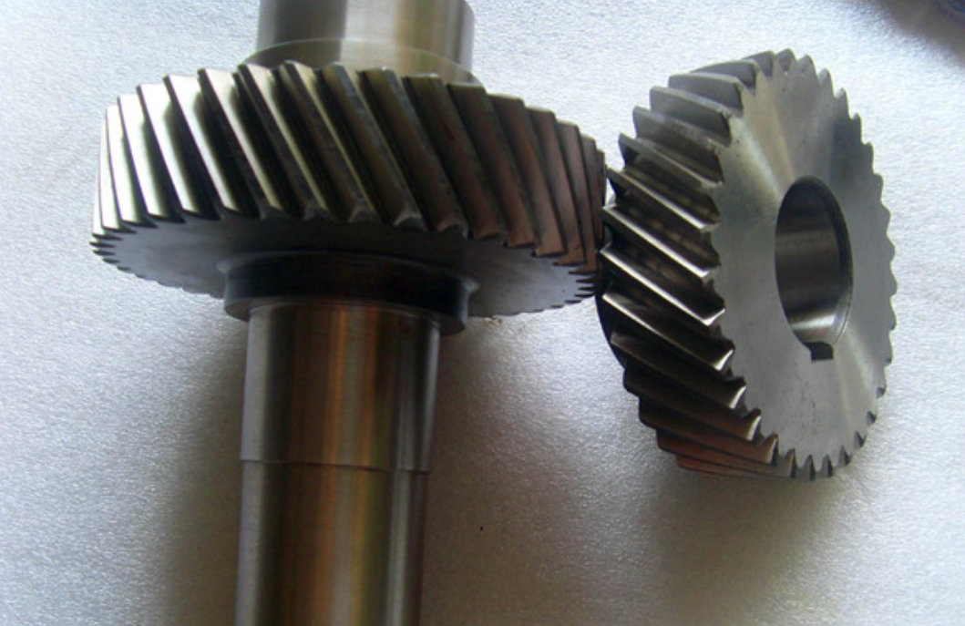
This study presents a comprehensive analysis of helical gear systems considering tooth profile and lead crowning modifications. A nonlinear coupling excitation model integrating stiffness and error dynamics is developed to investigate the effects of modification parameters on meshing stiffness, transmission error, and vibration response.
1. Modified Helical Gear Engagement Model
The meshing stiffness calculation for modified helical gears considers three-dimensional spatial effects through a sliced gear model. For each slice j, the equivalent stiffness is calculated as:
$$k_j = \frac{1}{\frac{1}{k_{t1}} + \frac{1}{k_{t2}} + \frac{1}{k_h}}$$
Where:
$$k_{ti} = \frac{1}{\frac{1}{k_{bi}} + \frac{1}{k_{si}} + \frac{1}{k_{ri}} + \frac{1}{k_{fi}}} \quad (i=1,2)$$
represents the comprehensive tooth stiffness including bending (kb), shear (ks), radial compression (kr), and foundation deformation (kf) components.

2. Modification Parameter Analysis
The combined modification profile incorporates both linear profile relief and circular lead crowning:
| Modification Type | Mathematical Expression | Key Parameters |
|---|---|---|
| Profile Relief | $$C_{ax} = C_a\left(\frac{x}{L_a}\right)$$ | Ca: Maximum relief amount La: Relief length |
| Lead Crowning | $$C_{cx} = \sqrt{r^2 – \left(\frac{b}{2} – L_c\right)^2} – \sqrt{r^2 – x^2}$$ | Cc: Crown amount Lc: Crowning length |
3. Stiffness and Error Characteristics
The parametric study reveals significant impacts of modification parameters:
| Parameter | Effect on Stiffness | Effect on Transmission Error |
|---|---|---|
| Profile Relief Amount (Ca) | Decreases mean stiffness | Increases amplitude |
| Profile Relief Length (La) | Nonlinear variation | Inverse relationship |
| Lead Crowning (Cc) | Reduces edge loading | Improves distribution |
The optimal modification parameters (Ca = 30μm, La = 6.4mm, Cc = 5μm, Lc = 5mm) demonstrate:
$$\sigma_k^2 \downarrow 96.69\% \quad \text{(Stiffness fluctuation reduction)}$$
4. Dynamic Response Analysis
The 12-DOF helical gear system model shows significant vibration reduction with proper modification:
| Operating Condition | Resonance Amplitude Reduction | Critical Speed Shift |
|---|---|---|
| Rated Speed (4100 rpm) | 42.7% | +5.8% |
| Variable Loading (0-1300Nm) | 38.9% | +3.2% |
The modified system’s acceleration frequency response follows:
$$A(f) = \frac{F_m}{\sqrt{(K_{eq} – m(2\pi f)^2)^2 + (c_{eq}2\pi f)^2}}$$
Where equivalent parameters incorporate modification effects.
5. Experimental Validation
Test results from a high-speed rail gearbox platform confirm:
| Performance Metric | Predicted | Measured | Error |
|---|---|---|---|
| Vibration Acceleration (m/s²) | 49.5 | 52.3 | 5.4% |
| Noise Level (dB) | 78.2 | 81.5 | 4.0% |
The proposed modification strategy effectively addresses the trade-off between stiffness maintenance and vibration suppression in helical gear systems, demonstrating superior performance in high-speed applications.
