
Abstract
Spiral bevel gear occupy a significant position in the mechanical industry, widely used in aviation, navigation, automobiles, and various precision machine tools. Due to their complex geometry and difficulty in controlling meshing quality, the application of numerical control (NC) machining technology has become an inevitable trend. Mechanical spiral bevel gear milling machines will gradually be replaced by NC milling machines.
This paper focuses on the NC reconstruction of the GH 35 spiral bevel gear milling machine using the GSK 980MDa system as an example. The innovation points and main research contents are as follows: 1) Analyzing the generating principle of the spiral bevel gear on the rocking-table milling machine, as well as the machine structure and corresponding motion relationships, a three-axis two-linkage NC reconstruction scheme is proposed. 2) Based on processing control requirements, the Guangzhou NC system GSK 980MDa is selected, and partial modifications are made to the mechanical parts of the machine tool. The machine’s main circuit, control circuit, and hydraulic control circuit are designed, and the PLC input and output interfaces within the NC system are allocated.
- Introduction
- 1.1 Introduction
- 1.2 Research Background and Significance
- 1.3 Current Research Status at Home and Abroad
- 1.3.1 Overview of the Development Status of NC Machine Tools
- 1.3.2 Overview of NC Machine Tool Reconstruction Technology
- 1.3.3 Overview of the Development of Spiral Bevel Gear Machining Machine Tools
- 1.4 Main Research Content of the Paper
- Cutting Principle of Spiral Bevel Gear Milling Machine
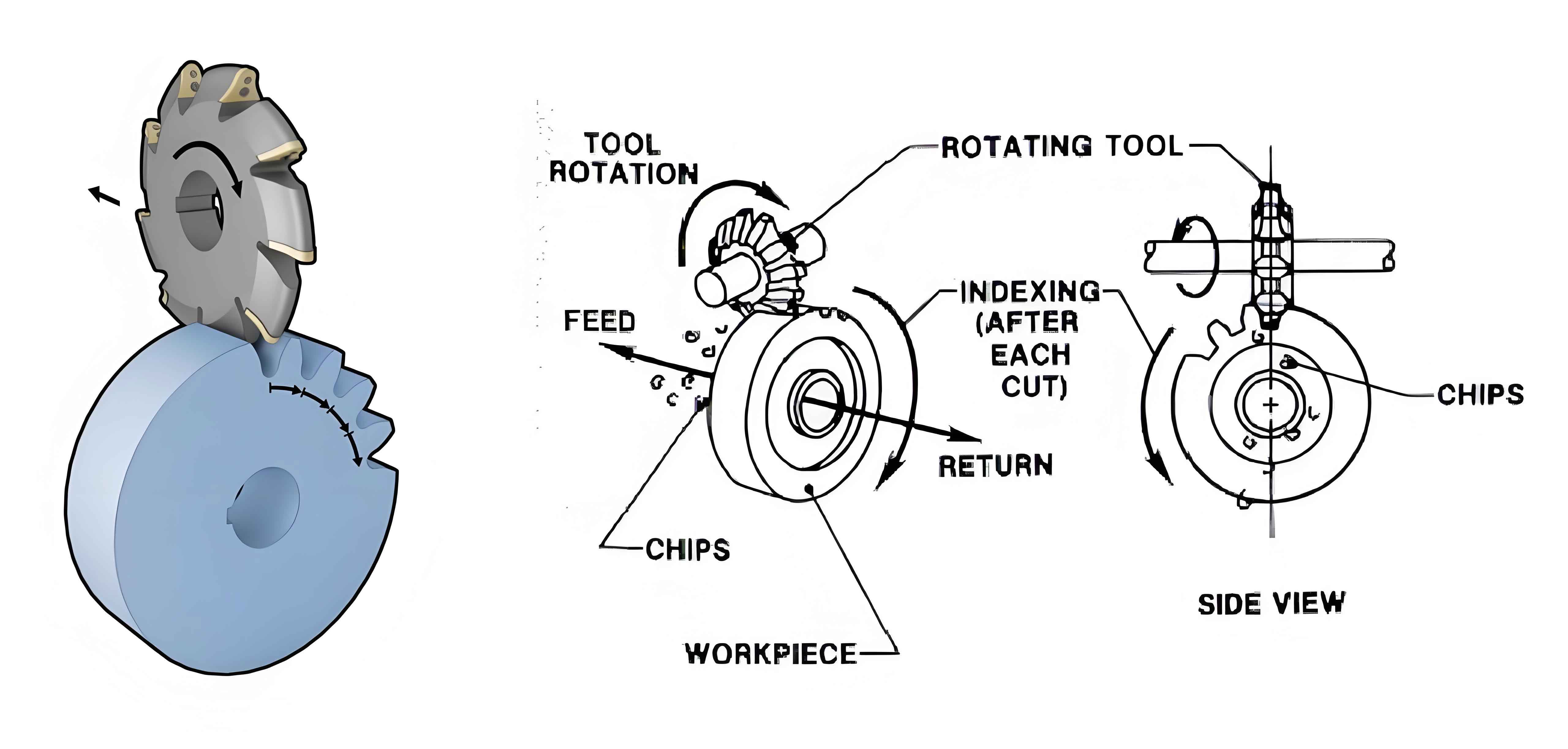
- 2.1 Generating Principle and Machining Method of Spiral Bevel Gear
- 2.1.1 Concept of Generating Wheel
- 2.1.2 Classification of Machining Methods
- 2.2 Machine Tool Structure and Motion Relationships
- 2.3 NC Reconstruction Overview of the GH 35 Milling Machine System
- 2.4 Summary of This Chapter
- 2.1 Generating Principle and Machining Method of Spiral Bevel Gear
Table 1: Classification of Machine Tool Reconstruction
| Type | Description |
|---|---|
| NC Upgrade | Adding display units, drive units, or electronic gearboxes to old machines |
| NC System Software and Hardware Upgrade | Upgrading without altering the original machine structure or NC system framework |
| Machine Tool Refurbishment | Refurbishing mechanical, hydraulic, and electrical control parts to improve accuracy and efficiency |
| Functional Innovation/Development | Developing new functions to adapt to new technologies and product types |
- Hardware Design for NC Reconstruction of GH 35 Spiral Bevel Gear Milling Machine
- 3.1 Introduction to NC System
- 3.1.1 NC System Upper Computer
- 3.1.2 Product Technical Characteristics
- 3.1.3 AC Servo Drive Devices
- 3.2 Mechanical Part Design of GH 35 Spiral Bevel Gear Milling Machine
- 3.2.1 NC Axis Mechanical Modification
- 3.2.2 Main Motion of the Machine Tool
- 3.2.3 Tooth Division and Micro-Feed Motion
- 3.2.4 Overall Structure of the Modified Machine Tool
- 3.3 Electrical Circuit Control Design
- 3.4 Hydraulic System Control Design
- 3.5 Summary of This Chapter
- 3.1 Introduction to NC System
Figure 1: NC Reconstruction System Structure Diagram of GH 35 Machine Tool
<img src=”https://example.com/nc_reconstruction_diagram.png” />
- NC System Software Development for GH 35 Milling Machine
- 4.1 Principle of GSK980Mda PLC
- 4.1.1 Program Execution Process
- 4.1.2 Sequential Program Structure
- 4.2 PLC Programming
- Input and Output Signal Distribution
- Example of Programming Logic
- 4.3 NC Macro Programming
- Macro Program Structure
- Application in Spiral Bevel Gear Machining
- 4.1 Principle of GSK980Mda PLC
Table 2: PLC Input/Output Signal Distribution
| Signal Name | PLC Input Address | Description |
|---|---|---|
| Work Clamp Switch | SA1 (X0.0) | Indicates when the work is clamped |
| Manual Advance Switch | SQ1 (X0.1) | Triggers manual advance of the workbench |
| Manual Retreat Switch | SQ2 (X0.2) | Triggers manual retreat of the workbench |
| Retreat Limit Switch | SQ3 (X0.3) | Stops retreat motion when triggered |
| Tool Setting Stroke Switch | SQ4 (X0.4) | Used for tool setting during machining |
| Start Machining Switch | SQ5 (X0.5) | Initiates machining process |
| Advance Limit Switch | SQ6 (X0.6) | Stops advance motion when triggered |
- Gear Milling Tests and Error Analysis
- 5.1 Gear Cutting Tests
- Description of the modified GH 35 machine in action
- Gear processing parameters and cutting process
- 5.2 Gear Inspection
- Methods for inspecting the cut gears
- Analysis of cutting errors and machine precision
- 5.1 Gear Cutting Tests
Figure 2: Photo of the Modified NC Machine Tool
<img src=”https://example.com/modified_nc_machine_tool.png” />
Table 3: Gear Processing Parameters
| Parameter | Value/Description |
|---|---|
| Gear Module | Specified value |
| Number of Teeth | Specified value |
| Helix Angle | Specified value |
| Material | Specified gear material |
| Cutting Tool Type | Double-sided or single-sided |
| Cutting Feed Parameters | Adjusted based on cutting needs |
- Conclusion
- Summarizes the research findings and contributions
- Discusses the significance and potential applications of the NC reconstruction work