
This study investigates the churning power losses in hypoid gears of passenger vehicle rear axles through advanced computational fluid dynamics (CFD) modeling. The research establishes a three-dimensional numerical framework to analyze oil-air interactions and proposes structural optimizations for enhanced transmission efficiency.
1. Numerical Methodology for Hypoid Gear Flow Analysis
The transient flow field in hypoid gear systems is governed by the fundamental conservation equations:
$$ \nabla \cdot \mathbf{V} = 0 \quad \text{(Continuity Equation)} $$
$$ \rho \frac{\partial \mathbf{V}}{\partial t} + \rho (\mathbf{V} \cdot \nabla)\mathbf{V} = -\nabla P + \mu \nabla^2 \mathbf{V} + \rho \mathbf{g} \quad \text{(Navier-Stokes Equation)} $$
The VOF model tracks the oil-air interface through phase fraction transport:
$$ \frac{\partial \alpha_{oil}}{\partial t} + \nabla \cdot (\alpha_{oil} \mathbf{V}) = 0 $$
where $\alpha_{oil}$ represents the oil volume fraction. Turbulence modeling employs the RNG k-ε equations:
$$ \frac{\partial (\rho k)}{\partial t} + \frac{\partial (\rho k u_i)}{\partial x_i} = \frac{\partial}{\partial x_j}\left(\alpha_k \mu_{eff} \frac{\partial k}{\partial x_j}\right) + G_k – \rho \epsilon $$
$$ \frac{\partial (\rho \epsilon)}{\partial t} + \frac{\partial (\rho \epsilon u_i)}{\partial x_i} = \frac{\partial}{\partial x_j}\left(\alpha_\epsilon \mu_{eff} \frac{\partial \epsilon}{\partial x_j}\right) + C_{1\epsilon}\frac{\epsilon}{k}G_k – C_{2\epsilon}\rho\frac{\epsilon^2}{k} $$
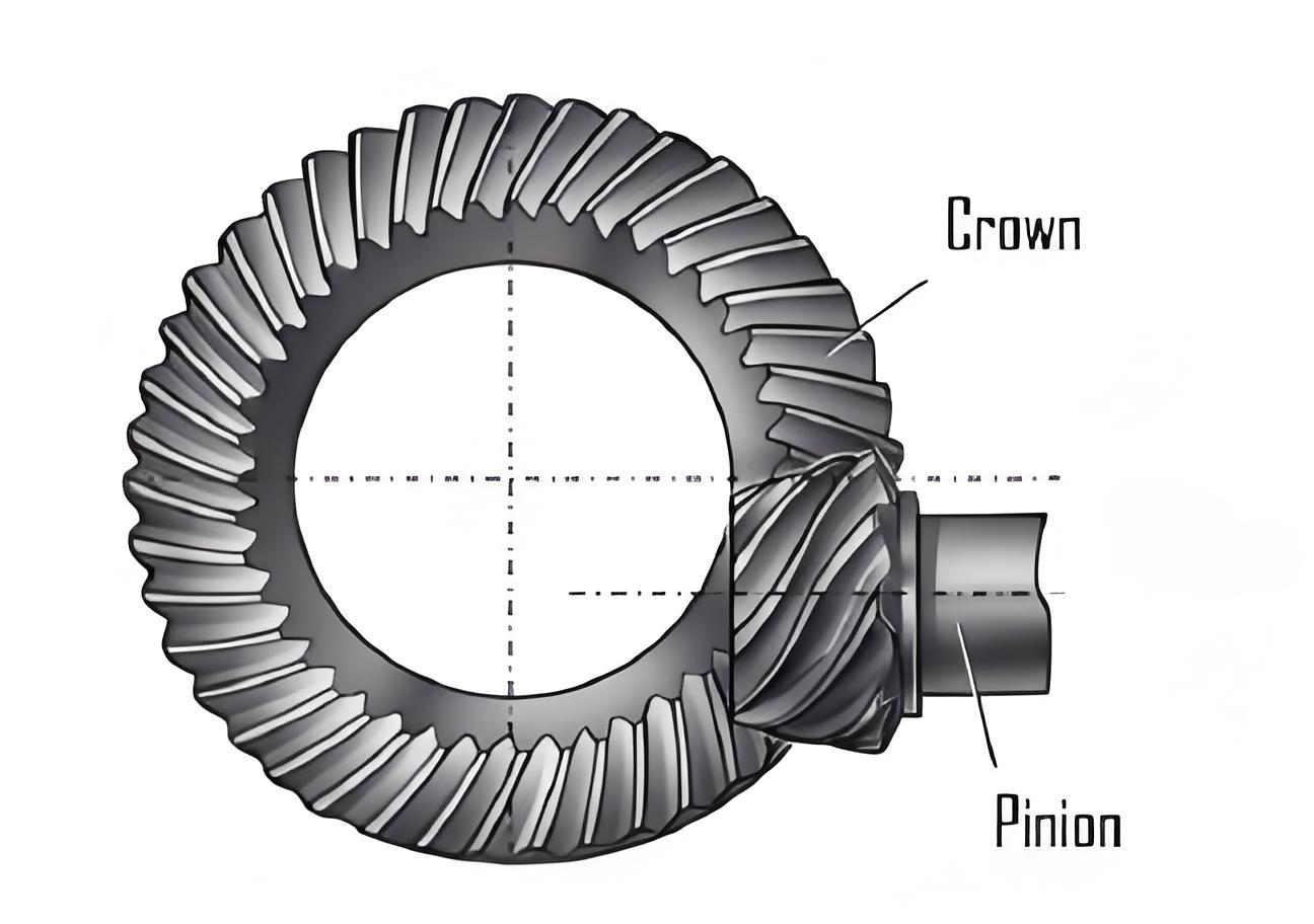
2. Hypoid Gear Churning Loss Characteristics
The numerical model reveals critical relationships between operating parameters and power losses:
| Speed (rpm) | Temperature (°C) | Churning Power (W) | Dynamic Pressure (kPa) |
|---|---|---|---|
| 133 | 90 | 18.2 | 1.46 |
| 444 | 60 | 74.5 | 7.50 |
| 888 | 30 | 237.2 | 23.72 |
3. Structural Optimization Strategy
Comparative analysis of bolt configurations demonstrates significant improvements:
$$ \Delta P_{loss} = \frac{P_{standard} – P_{countersunk}}{P_{standard}} \times 100\% $$
| Speed (rpm) | Standard Bolt (W) | Countersunk Bolt (W) | Loss Reduction (%) |
|---|---|---|---|
| 444 | 74.5 | 71.3 | 4.3 |
| 621 | 128.6 | 118.4 | 7.9 |
| 888 | 237.2 | 222.7 | 6.1 |
4. Validation Through Efficiency Testing
Bench tests confirm the numerical predictions for hypoid gear efficiency improvement:
$$ \eta_{improved} = \eta_{baseline} + \Delta \eta $$
$$ \Delta \eta \in [1.0\%, 1.1\%] \quad \text{across operational range} $$
5. Conclusion
This comprehensive investigation establishes that hypoid gear churning losses exhibit:
- Quadratic relationship with rotational speed ($P_{loss} \propto \omega^{1.8}$)
- Inverse correlation with lubricant temperature
- Significant sensitivity to protrusion features (bolts)
The countersunk bolt modification demonstrates 6-8% churning power reduction, achieving measurable efficiency gains in hypoid gear transmission systems.