1. Introduction
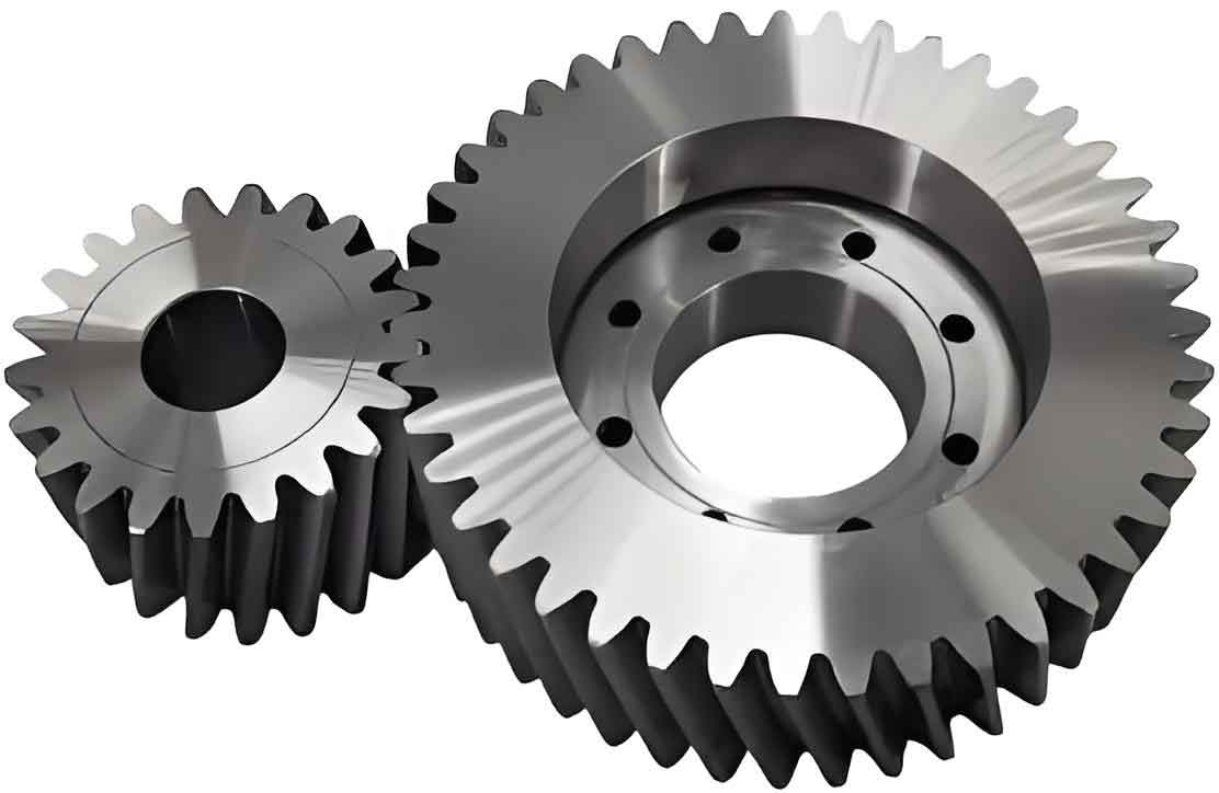
Cylindrical gears are fundamental components in mechanical transmission systems, widely used in automotive, aerospace, and industrial machinery. The rolling forming process has emerged as a critical manufacturing technique due to its advantages in improving material utilization, enhancing fatigue strength, and reducing post-processing requirements. However, defects such as lugs—protrusions at the tooth tips—remain a significant challenge in achieving high-precision cylindrical gears. This study focuses on the numerical simulation of the hot rolling process for cylindrical gears using DEFORM software, analyzing stress-strain distributions, rolling forces, and the formation mechanisms of lug defects. By optimizing process parameters, particularly the friction coefficient, this research aims to provide theoretical and practical insights for industrial applications.

2. Literature Review
Recent advancements in gear rolling technology highlight the importance of numerical simulations and parameter optimization. Key studies include:
| Author(s) | Contribution | Relevance to Cylindrical Gears |
|---|---|---|
| NISTOR et al. [5] | Studied deformation mechanisms and validated simulation results with experiments. | Validated stress distribution models. |
| SIECZKAREK et al. [6] | Optimized friction and blank-cutting strategies to address underfilling defects. | Highlighted friction’s role in defect control. |
| BREUCHER et al. [7] | Analyzed rolling parameters for gears of varying specifications using FEM. | Established a framework for parameter studies. |
| ZHU Xiao-xing et al. [10] | Investigated metal flow influenced by relative sliding between tooth profiles. | Linked sliding effects to lug formation. |
| LIU Hui-min [12] | Proposed tooth modification schemes to enhance rolling quality. | Emphasized geometric accuracy in cylindrical gears. |
These studies collectively underscore the need for integrated simulations and friction optimization to mitigate defects in cylindrical gear manufacturing.
3. Modeling of the Rolling Process
3.1 Tooth Surface Equation Derivation
The involute profile of cylindrical gears is mathematically defined in the end-face coordinate system. For a base circle radius rbrb, the parametric equations for the left and right involutes are:ra(θs,ua)=[±rb[sin(θ0+θs)−θscos(θ0+θs)]−rb[cos(θ0+θs)+θssin(θ0+θs)]ua1]ra(θs,ua)=±rb[sin(θ0+θs)−θscos(θ0+θs)]−rb[cos(θ0+θs)+θssin(θ0+θs)]ua1
where θsθs is the involute parameter, uaua is the axial coordinate, and θ0θ0 is the initial angle.
3.2 Rolling Process Stages
The rolling forming of cylindrical gears comprises three stages:
- Splitting Stage: Initial indentation of the blank by the mold wheel.
- Forming Stage: Radial feed increases to shape the tooth profile via plastic flow.
- Finishing Stage: Oscillatory motion refines the tooth geometry without further feed.
Table 1: Key Parameters for Mold and Target Gears
| Parameter | Mold Wheel | Target Gear |
|---|---|---|
| Module (mm) | 2 | 2 |
| Pressure Angle (°) | 20 | 20 |
| Number of Teeth | 53 | 19 |
| Addendum Coefficient | 1 | 1 |
| Tip Clearance Coefficient | 0.25 | 0.25 |
4. Numerical Simulation Analysis
4.1 Stress and Strain Distribution
Using DEFORM-3D, the equivalent stress and strain fields were analyzed at different feed stages (30%, 60%, 100%, and finishing). Key findings include:
- Maximum Strain: Occurs at the root of the blank’s tooth during forming.
- Maximum Stress: Peaks at the mold-blank contact region, reaching 347 MPa at 100% feed.
Table 2: Stress Evolution Across Stages
| Stage | Max Stress (MPa) | Strain Localization |
|---|---|---|
| Splitting | 309 | Tooth root |
| Forming | 342 | Mold-blank interface |
| 100% Feed | 347 | Internal diffusion |
| Finishing | 250 | Stabilized distribution |
4.2 Rolling Force Trends
Rolling forces in X, Y, and Z directions were monitored. The Y-direction force was negligible, while X and Z forces exhibited a rising trend due to increasing metal resistance.
Equation for Rolling Force (FF):F=∫t1t2(σ⋅ϵ˙)dtF=∫t1t2(σ⋅ϵ˙)dt
where σσ is stress and ϵ˙ϵ˙ is strain rate.
5. Lug Defect Formation and Control
5.1 Mechanism of Lug Formation
Lugs arise from mismatched rotational speeds between the mold wheel and blank, causing excessive material flow at the tooth tip. Forces NACNAC, fACfAC, NBCNBC, and fBCfBC create asymmetric deformation during mold disengagement.
5.2 Friction Coefficient Optimization
Friction significantly influences lug severity. Simulations with varying friction coefficients (μμ) revealed:
Table 3: Friction vs. Lug Height
| μμ | Lug Height (mm) | Severity |
|---|---|---|
| 0.1 | 0.15 | Low |
| 0.2 | 0.37 | Moderate |
| 0.3 | 0.62 | High |
Optimal μ=0.15–0.18μ=0.15–0.18 minimizes lugs while ensuring stable forming.
6. Industrial Implications
This study provides actionable strategies for cylindrical gear manufacturers:
- Precision Feed Control: Synchronize mold and blank rotations to reduce speed mismatch.
- Lubrication Optimization: Use low-friction coatings (μ<0.2μ<0.2) to suppress lugs.
- Multi-Stage Refinement: Implement iterative simulations to balance efficiency and quality.
7. Conclusion
By integrating numerical simulations with parameter optimization, this research advances the understanding of stress-strain dynamics and defect control in cylindrical gear rolling. Future work will explore real-time monitoring systems and AI-driven process adjustments to further enhance manufacturing precision.
