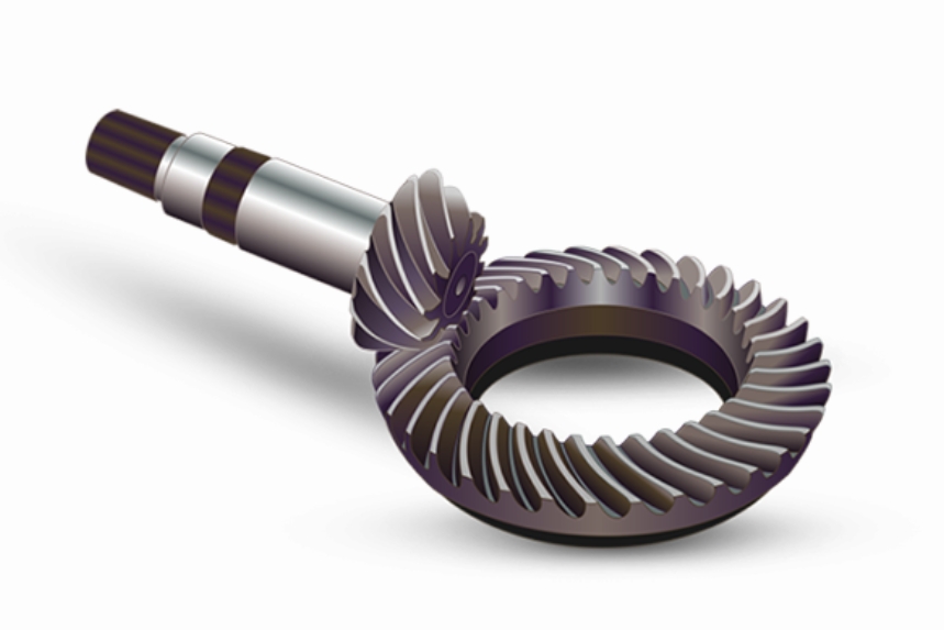
Shot peening is a critical surface enhancement process for spiral bevel gears, inducing compressive residual stresses to improve fatigue life. This study establishes a coupled discrete element method (DEM) and finite element method (FEM) model to predict residual stress distributions in AISI 9310 steel spiral bevel gears. Experimental validation confirms the model’s accuracy with errors below 10%, enabling systematic exploration of shot peening parameter effects.

Fundamental Mechanisms and Modeling Approach
The residual stress generation mechanism follows the relationship:
$$ \sigma_{\text{res}} = f(E, \varepsilon_p, \dot{\varepsilon}, T) $$
where \( E \) represents Young’s modulus, \( \varepsilon_p \) plastic strain, \( \dot{\varepsilon} \) strain rate, and \( T \) temperature. The Johnson-Cook constitutive model describes material behavior:
$$ \sigma = (A + B\varepsilon^n)\left(1 + C\ln\frac{\dot{\varepsilon}}{\dot{\varepsilon}_0}\right)\left(1 – (T^*)^m\right) $$
with material constants for 9310 steel: \( A = 1234.38 \, \text{MPa} \), \( B = 881 \), \( n = 0.238 \), \( C = 0.018 \), \( m = 0.686 \).
Coupled DEM-FEM Simulation Framework
The integrated modeling approach consists of three phases:
| Phase | Component | Key Parameters |
|---|---|---|
| DEM | Particle dynamics | Shot velocity: 30–50 m/s Diameter: 0.18–0.42 mm Coverage: 98–200% |
| Data Mapping | Impact statistics | Velocity vectors Impact density: 360–720/mm² |
| FEM | Stress analysis | Element size: 10 μm Infinite elements: CIN3D8 Damping: \( \alpha = 6 \times 10^6 \, \text{s}^{-1} \) |
Experimental Validation
Residual stress measurements at critical positions demonstrate strong agreement between simulation and X-ray diffraction results:
| Position | σx Surface (MPa) | σy Surface (MPa) | Error |
|---|---|---|---|
| Convex (b) | -824.2 | -805.3 | 2.3% |
| Concave (b) | -837.9 | -849.7 | 1.4% |
Parameter Sensitivity Analysis
The spiral bevel gear’s residual stress profile shows distinct responses to process parameters:
1. Peening Duration Effects
$$ N_{\text{imp}} = \frac{\dot{m}t}{\frac{4}{3}\pi r^3\rho} $$
where \( \dot{m} \) = mass flow rate (5 kg/min), \( r \) = shot radius. At 200% coverage:
| Depth (μm) | 72 s | 144 s | Δ Stress |
|---|---|---|---|
| Surface | -798 | -826 | 3.5% |
| 20 | -1045 | -1128 | 8.0% |
| 40 | -672 | -743 | 10.6% |
2. Shot Velocity Impact
Velocity calculation from pneumatic parameters:
$$ v = \frac{163.5P}{1.53q_m + 10P} + \frac{295P}{0.598d + P} + 48.3P $$
Increasing velocity from 30 to 50 m/s enhances subsurface compression:
| Velocity (m/s) | σmax (MPa) | Depth (μm) |
|---|---|---|
| 30 | -1104.7 | 20 |
| 40 | -1144.9 | 25 |
| 50 | -1167.3 | 30 |
3. Shot Diameter Optimization
Larger shots increase penetration depth while maintaining surface finish:
| Diameter (mm) | Surface Sa (μm) | σmax (MPa) | Depth (μm) |
|---|---|---|---|
| 0.18 | 0.32 | -893.6 | 10 |
| 0.30 | 0.39 | -1145.0 | 30 |
| 0.42 | 0.47 | -1251.5 | 40 |
Process Optimization Guidelines
For spiral bevel gears requiring >107 cycle fatigue life:
$$ \text{Optimal Parameters} = \begin{cases}
v \geq 40 \, \text{m/s} \\
d = 0.30 \, \text{mm} \\
t \geq 120 \, \text{s}
\end{cases} $$
This combination achieves surface compression >-800 MPa with 30–40 μm effective depth, balancing processing efficiency and surface integrity.
Industrial Implementation
The validated model enables predictive process design for spiral bevel gears without iterative trials. Key implementation steps:
- Import gear CAD model
- Define material properties
- Set DEM boundary conditions
- Run coupled simulation
- Extract residual stress tensor
- Verify against fatigue requirements
Future development will integrate machine learning for real-time parameter adjustment during spiral bevel gear peening operations.
