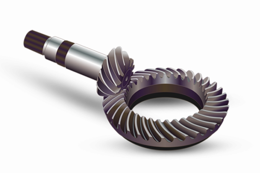
This study proposes a numerical simulation and parameter optimization method for warm rolling of spiral bevel gear pinions to address challenges in traditional manufacturing processes. A finite element model was established to analyze the influence of friction factor, feed rate, and initial rolling temperature on forming quality, supported by orthogonal experiments and physical verification.
1. Mathematical Modeling of Warm Rolling Process
The tooth surface generation mechanism follows conjugate meshing principles. For spiral bevel gears with design parameters (Table 1), the coordinate transformation matrices between pinion and tool gear are expressed as:
$$ \mathbf{M}_{2d} = \begin{bmatrix}
1 & 0 & 0 & 0 \\
0 & -\cos\phi_2 & -\sin\phi_2 & 0 \\
0 & \sin\phi_2 & -\cos\phi_2 & 0 \\
0 & 0 & 0 & 1
\end{bmatrix}, \quad \mathbf{M}_{dh} = \begin{bmatrix}
\cos\Gamma & 0 & -\sin\Gamma & 0 \\
0 & 1 & 0 & -E \\
\sin\Gamma & 0 & \cos\Gamma & 0 \\
0 & 0 & 0 & 1
\end{bmatrix} $$
The equivalent strain energy density during plastic deformation is calculated as:
$$ \bar{\sigma} = \sqrt{\frac{3}{2}\sigma_{ij}’\sigma_{ij}’} $$
$$ \bar{\varepsilon} = \sqrt{\frac{2}{3}\varepsilon_{ij}\varepsilon_{ij}} $$

2. Parameter Sensitivity Analysis
The orthogonal experimental design (Table 2) reveals significant parameter interactions affecting spiral bevel gear forming quality:
| Factor | Level 1 | Level 2 | Level 3 | Range (R) |
|---|---|---|---|---|
| Friction (A) | 1,348.5 MPa | 1,318.5 MPa | 1,288.5 MPa | 60 |
| Feed Rate (B) | 1,272.5 MPa | 1,318.5 MPa | 1,364.5 MPa | 92 |
| Temperature (C) | 1,396.0 MPa | 1,318.5 MPa | 1,241.0 MPa | 155 |
The parameter influence hierarchy follows:
$$ R_C > R_B > R_A \quad (155 > 92 > 60) $$
3. Process Window Optimization
Optimal parameters for spiral bevel gear warm rolling were determined through response surface analysis:
$$ \text{Minimize } \Psi = \alpha\bar{\sigma} + \beta\bar{\varepsilon} $$
$$ \text{Subject to: } 0.2 \leq \mu \leq 0.4 $$
$$ 0.1 \, \text{mm/s} \leq v \leq 0.3 \, \text{mm/s} $$
$$ 600^\circ C \leq T \leq 700^\circ C $$
The optimized solution yields:
$$ \mu^* = 0.4, \quad v^* = 0.1 \, \text{mm/s}, \quad T^* = 700^\circ C $$
4. Experimental Validation
Physical tests using optimized parameters achieved precision class GB 8 with geometric deviations:
| Surface | Total Deviation (μm) | Pitch Error (μm) |
|---|---|---|
| Convex | 14.4 | 57.0 |
| Concave | 14.1 | 56.3 |
The developed methodology demonstrates significant improvements in spiral bevel gear manufacturing efficiency and precision, particularly suitable for high-performance automotive and aerospace applications requiring tight tolerances.
