
1. Establishment of finite element model
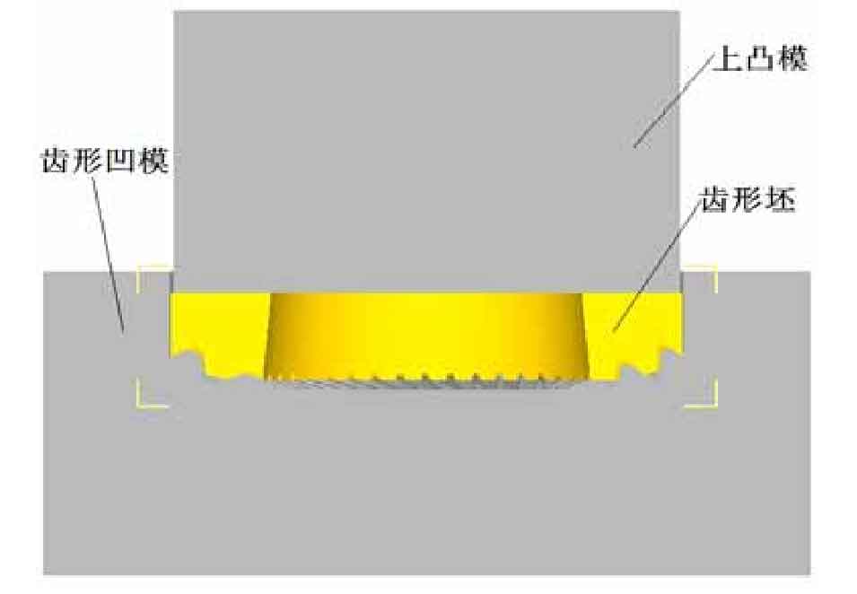
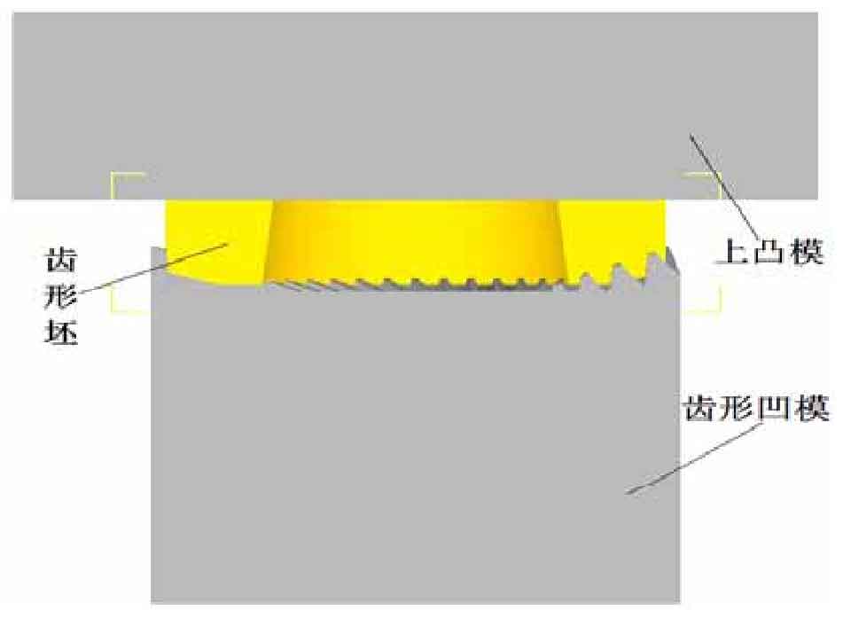
According to the structural diagram of closed cold finishing and open cold finishing, the solid model is established by using 3D modeling software UG. After the established solid model is exported into STL graphics, it is imported into DEFORM-3D software to establish the finite element model. Because the tooth profile of spiral bevel gear is arc-shaped and not axisymmetric, the whole is selected as the model for numerical simulation analysis. Figures 1 and 2 are the sectional diagrams of closed cold finishing and open cold finishing finite element models respectively.
2. Determination of forming scheme
Under the condition of ensuring the same volume and shape of spiral bevel gear tooth blank, the two forming process schemes are numerically simulated by using DEFORM-3D finite element numerical simulation software. The numerical simulation results are checked and analyzed in the post-processing, and the forming force stroke curves of different forming schemes are obtained, as shown in Fig. 3. The dotted line in the figure is the stroke load curve obtained by adopting finishing scheme I (closed cold finishing process scheme), and the solid line is the stroke load curve obtained by adopting finishing scheme II (open cold finishing process scheme). It can be seen from the stroke load curve of scheme 1 and scheme 2 that the cold finishing of the tooth profile of spiral bevel gear is mainly divided into three stages:
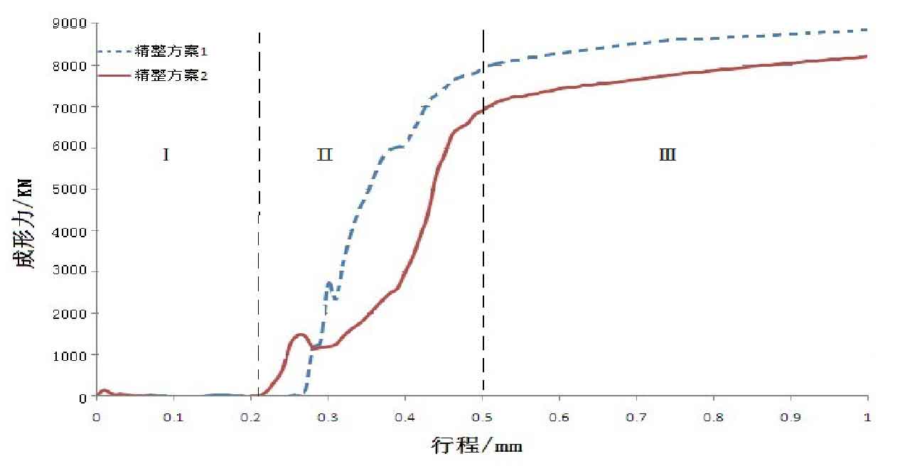
The first stage is the spiral bevel gear tooth shape, and the tooth shape of the blank is gradually in contact with the tooth shape cavity of the female die. At this time, the tooth shape part has not been hindered by the tooth shape cavity of the female die, and the required forming force is small.
The second stage is the cold finishing stage of the tooth profile of spiral bevel gear. With the continuous increase of the pressing amount of the punch, the metal materials at the tooth shape part are in contact with the tooth shape cavity of the female die. At this time, greater forming force is required to force the plastic deformation of the tooth shape, so that part of the metal flows to the tooth shape cavity of the female die and part of the metal flows to the large and small ends of the tooth shape die, so as to eliminate the defects at the tooth shape part of the spiral bevel gear and reach or close to the required specifications and dimensions of the parts, The forming force at this stage rises sharply.
The third stage is the end stage of cold finishing. Through the cold finishing of the tooth profile of the spiral bevel gear in the second stage, the metal on the tooth surface flows and fills the cavity of the tooth profile of the female die, while the excess metal material flows directly from the large and small ends of the spiral bevel gear tooth profile die, and the forming force in this stage tends to rise steadily.
It can be seen from Figure 3 that the forming force of scheme II (open cold finishing) is 8220kn and that of scheme I (closed cold finishing) is 8860kn. It can be seen that the forming force of scheme II is lower than that of scheme I, which is 7.22% lower than that of scheme I. This is because in the process of finishing the tooth profile with the closed cold finishing scheme, the excess metal material can not flow out in time, resulting in the increase of forming force. Although the processing amount of the outer circular surface of the formed parts formed by the closed cold finishing scheme is less in the subsequent processing, considering that in the cold finishing process of the tooth profile of the spiral bevel gear, if the forming force is too large, it will cause the wear of the die tooth profile and even cause the cracking of the die, which will reduce the service life of the die. Therefore, in the research of cold finishing, it is also reasonable to adopt the open cold finishing process with the goal of reducing the forming force.