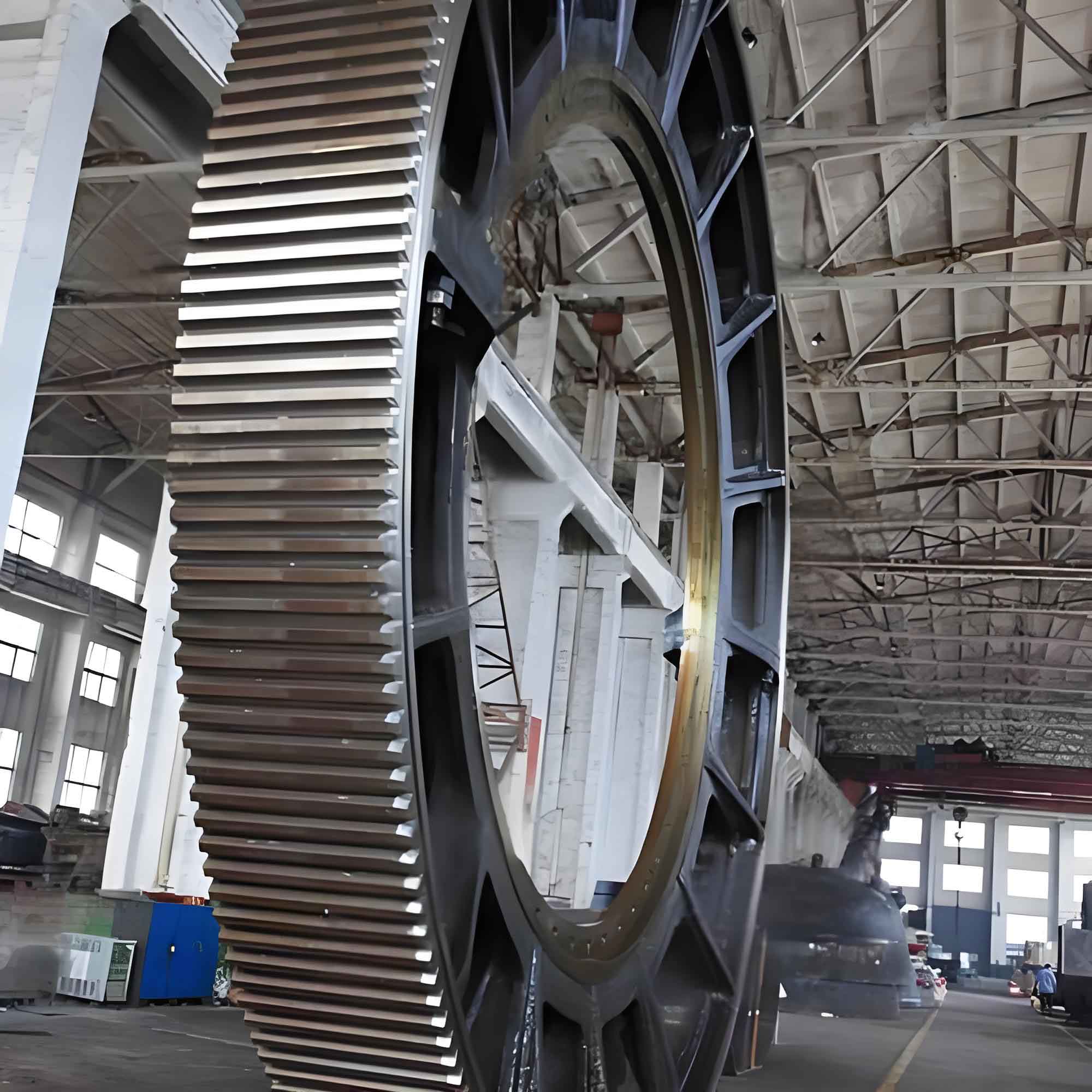
Large gears are critical components in heavy machinery, with their lifespan directly impacting operational efficiency. Surface hardening through local induction heating enhances wear resistance in high-stress areas. This study investigates the temperature and stress distributions during induction heating of large spur gears using a novel electromagnetic setup validated through experimental and numerical methods.
The governing equations for transient temperature distribution incorporate temperature-dependent material properties:
$$ \frac{\partial}{\partial x} \left( \lambda \frac{\partial T}{\partial x} \right) + \frac{\partial}{\partial y} \left( \lambda \frac{\partial T}{\partial y} \right) + \frac{\partial}{\partial z} \left( \lambda \frac{\partial T}{\partial z} \right) + Q = \rho c \frac{\partial T}{\partial t} $$
where $\lambda$ = thermal conductivity (W/m·K), $Q$ = internal heat generation (W/m³), $\rho$ = density (kg/m³), $c$ = specific heat (J/kg·K). Boundary conditions account for convective and radiative heat transfer:
$$ \lambda \frac{\partial T}{\partial n} = -h(T – T_B) – \varepsilon \sigma (T^4 – T_B^4) $$
Thermal stress analysis follows the Prandtl-Reuss theory with Mises yield criterion:
$$ \sigma = H \left( \int d\varepsilon^P, T \right) $$
Incremental stress-strain relationships differentiate elastic and plastic regions:
| Region | Constitutive Equation |
|---|---|
| Elastic | $\Delta\{\sigma\} = [D](\Delta\{\varepsilon\} – \Delta\{\varepsilon\}_T)$ |
| Plastic | $\Delta\{\sigma\} = [D]_{ep}(\Delta\{\varepsilon\} – \Delta\{\varepsilon\}_T) + \Delta\{\sigma\}_T$ |
Uniformity metrics quantify temperature ($U_T$) and stress ($U_\sigma$) distributions:
$$ \sigma_{\text{metric}} = \sqrt{ \frac{1}{N} \sum_{i=1}^{N} (X_i – \bar{X})^2 }, \quad U = \left(1 – \frac{\sigma_{\text{metric}}}{\bar{X}}\right) \times 100\% $$

Experimental validation used 45 steel plates (200×200×10 mm) with the novel induction system. Power density reached 1.2×10⁸ W/m³ at 15 kHz frequency. Temperature measurements showed <10% deviation from simulations, confirming model accuracy for subsequent large gear analysis.
The large gear model (module=40, teeth=35, width=80mm) used refined meshing near the tooth surface. Two coil positioning schemes were analyzed:
| Scheme | Coil Orientation | Ferrite Coverage |
|---|---|---|
| 1 | Perpendicular to tooth axis | Partial |
| 2 | Parallel to tooth axis | Full |
Temperature evolution revealed distinct phases:
$$ \frac{dT}{dt} = \begin{cases}
> 150^\circ \text{C/s} & \text{(pre-Curie point)} \\
< 20^\circ \text{C/s} & \text{(post-Curie point)}
\end{cases} $$
For the large gear, peak temperature (768°C) occurred at 1.7s at the projection center (Point O). Thermal stress evolution showed inverse behavior to temperature:
| Time (s) | Max Stress (MPa) | Location |
|---|---|---|
| 0.4 | 354.16 (Scheme 1) | Point O |
| 0.4 | 355.11 (Scheme 2) | Point O |
| 5.0 | <220 | All regions |
Temperature uniformity decreased initially due to rapid differential heating, then recovered through thermal conduction. Stress uniformity exhibited oscillatory behavior as different regions sequentially yielded:
$$ U_\sigma(t) = U_{\sigma,\max} \cdot e^{-kt} \sin(\omega t + \phi) $$
At t=5s, uniformity metrics converged:
| Scheme | Temp. Uniformity (%) | Stress Uniformity (%) |
|---|---|---|
| 1 | 92.62 | 91.78 |
| 2 | 90.28 | 97.90 |
Scheme 1 achieved superior temperature homogeneity in the large gear (92.62% vs 90.28%), while Scheme 2 produced more uniform stress fields (97.9% vs 91.78%). The phase shift between temperature and stress uniformity exceeded 1.5s due to delayed plastic deformation responses.
Optimal processing parameters for large gear hardening were derived from uniformity convergence patterns:
$$ t_{\text{optimal}} = 5.0 \pm 0.3 \text{s}, \quad P_{\text{density}} = 1.0 \times 10^8 \text{ W/m}^3 $$
These findings demonstrate the novel induction system’s efficacy for large gear surface hardening. The inverse relationship between temperature and stress uniformity necessitates independent optimization of both parameters when designing heat treatment processes for large gears operating under extreme loads.
