1. Introduction
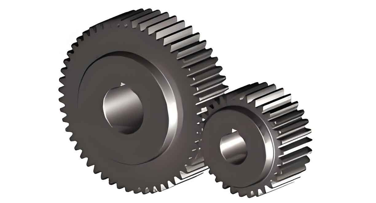
As a critical component in mechanical transmission systems, spur gears directly influence the operational efficiency and longevity of heavy machinery. With the growing demand for large-scale industrial equipment, enhancing the durability of spur gears has become a focal point for researchers and engineers. Surface hardening through localized induction heating is a widely adopted method to mitigate gear failure caused by bending stress, contact fatigue, and wear. However, achieving uniform temperature and stress distributions during the heating process remains a significant challenge.
In this study, I explore the numerical simulation of the local induction heating process for large spur gears using ANSYS APDL. By comparing two distinct heating schemes, I aim to evaluate their temperature and stress uniformity, providing insights for optimizing gear surface hardening.

2. Mathematical Model
2.1 Transient Temperature Field
The induction heating process involves rapid temperature fluctuations and nonlinear material properties. The governing equation for 3D transient heat conduction is:∂∂x(λ∂T∂x)+∂∂y(λ∂T∂y)+∂∂z(λ∂T∂z)+Q=ρc∂T∂t∂x∂(λ∂x∂T)+∂y∂(λ∂y∂T)+∂z∂(λ∂z∂T)+Q=ρc∂t∂T
Key Parameters:
- λλ: Temperature-dependent thermal conductivity
- QQ: Internal heat source intensity
- ρρ: Material density
- cc: Temperature-dependent specific heat capacity
Boundary conditions include convective and radiative heat transfer at the gear surface:λ∂T∂n=h(T−TB)+ϵσ(T4−TB4)λ∂n∂T=h(T−TB)+ϵσ(T4−TB4)
2.2 Transient Stress Field
Thermal stresses arise from non-uniform temperature distributions. Using the Prandtl-Reuss incremental theory and Mises yield criterion, the stress-strain relationship is expressed as:
Elastic Region:Δ{σ}=[D](Δ{ϵ}−Δ{ϵ}T)Δ{σ}=[D](Δ{ϵ}−Δ{ϵ}T)
Plastic Region:Δ{σ}=[D]ep(Δ{ϵ}−Δ{ϵ}T)+Δ{σ}TΔ{σ}=[D]ep(Δ{ϵ}−Δ{ϵ}T)+Δ{σ}T
Key Variables:
- [D][D]: Elasticity matrix
- [D]ep[D]ep: Elastoplasticity matrix
- Δ{ϵ}TΔ{ϵ}T: Thermal strain increment
2.3 Uniformity Metrics
Temperature and stress uniformity are quantified using standard deviation (σσ) and uniformity index:Uniformity=(1−σXˉ)×100Uniformity=(1−Xˉσ)×100
3. Experimental Setup and Simulation
3.1 Material and Induction Heating Device
- Material: 45 steel (properties listed in Table 1).
- Gear Specifications:
- Module: 40
- Number of teeth: 35
- Tooth width: 80 mm
Table 1: Material Properties of 45 Steel
| Property | Value |
|---|---|
| Density (ρρ) | 7850 kg/m³ |
| Thermal Conductivity | 48 W/m·K (20°C) |
| Specific Heat Capacity | 475 J/kg·K |
| Yield Strength | 355 MPa (at 20°C) |
3.2 Finite Element Model
- Mesh Strategy:
- Surface layer (0–4 mm): Fine uniform mesh.
- Core region (4 mm inward): Coarse graded mesh.
- Tooth tip: Mapped mesh.
- Element Types:
- SOLID236 (harmonic magnetic field).
- SOLID90 (temperature field).
- SOLID186 (stress field).
3.3 Heating Schemes
Two induction coil configurations were analyzed:
- Scheme 1: Coil positioned axially above the tooth center.
- Scheme 2: Coil offset slightly to enhance lateral heating.
4. Results and Discussion
4.1 Temperature Field Analysis
- Temperature distribution at 5 s for both schemes.
- Highest temperature observed at the coil projection center (O point).
- Rapid heating phase (0–1.7 s) followed by stabilization due to material demagnetization.
Table 2: Temperature Uniformity at 5 s
| Scheme | Uniformity (%) |
|---|---|
| 1 | 92.62 |
| 2 | 90.28 |
4.2 Thermal Stress Field Analysis
- Stress evolution at key observation points.
- Peak stress (~355 MPa) occurs at 0.4 s, exceeding yield strength and inducing plasticity.
- Stress uniformity improves post-yield due to plastic deformation.
Table 3: Stress Uniformity at 5 s
| Scheme | Uniformity (%) |
|---|---|
| 1 | 91.78 |
| 2 | 97.90 |
4.3 Comparative Analysis
- Scheme 1 achieves better temperature uniformity, while Scheme 2 excels in stress uniformity.
- Divergent trends in temperature and stress uniformity over time.
5. Conclusion
- The ANSYS-based model effectively simulates the induction heating process for large spur gears, capturing transient temperature and stress behaviors.
- Temperature uniformity peaks at 92.62% (Scheme 1), whereas stress uniformity reaches 97.9% (Scheme 2).
- The asynchronous evolution of temperature and stress uniformity underscores the need for multi-objective optimization in gear hardening processes.
