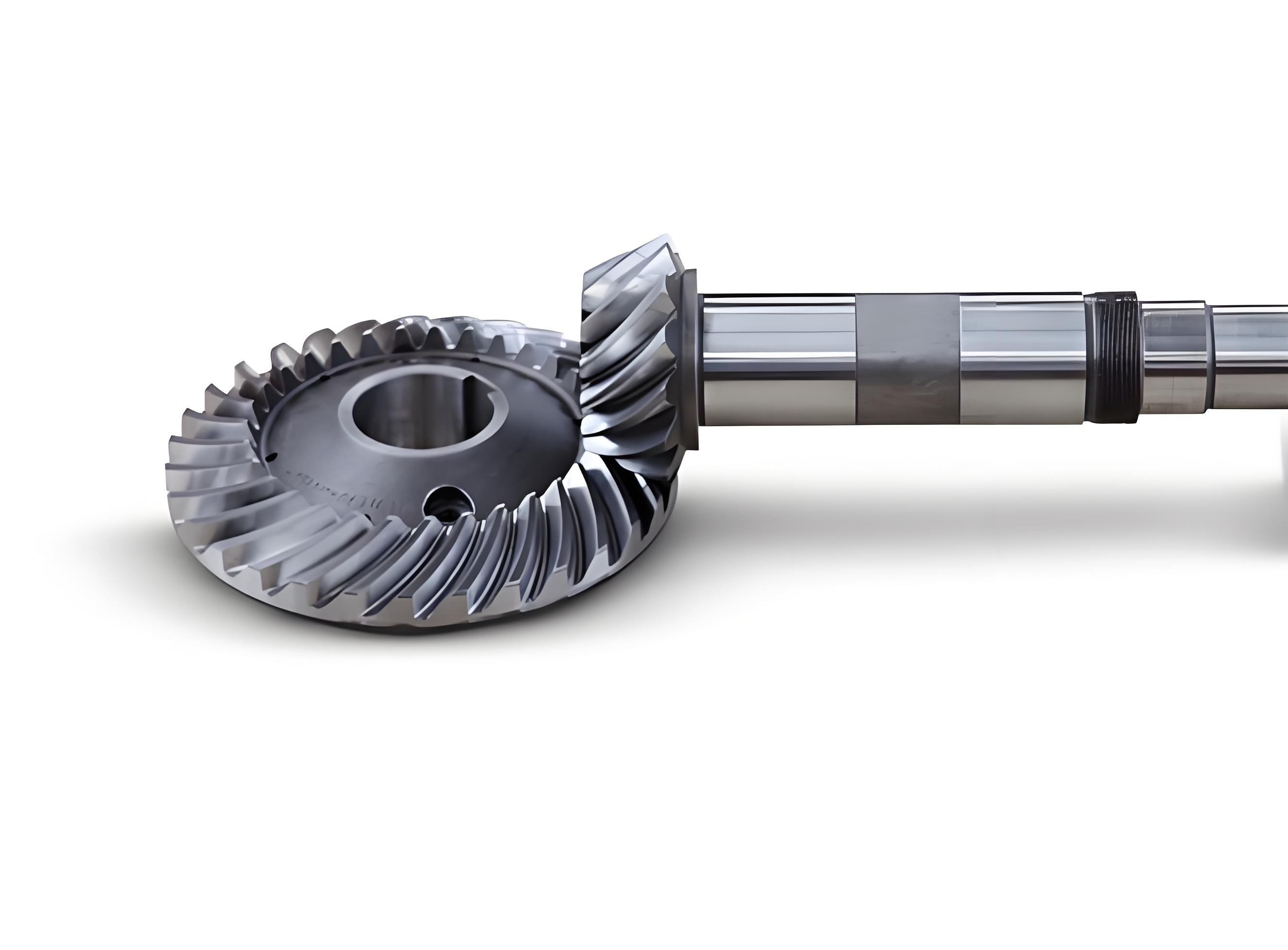
This study investigates the quenching behavior of 45 steel spiral bevel gears using thermo-fluid-solid coupling simulation, focusing on the influence of quenching medium flow velocity. The spiral bevel gear geometry parameters are summarized in Table 1, with key features illustrated through computational modeling:

| Parameter | Value | Parameter | Value |
|---|---|---|---|
| Number of teeth | 20 | Tooth face width | 23 mm |
| Module | 4 mm | Mean pressure angle | 20° |
| Spiral angle | 35° | Pitch diameter | Ø65 mm |
1. Thermo-Fluid-Solid Coupling Framework
The governing equations for fluid-solid interaction at the coupling interface are expressed as:
$$y^+ \equiv \frac{\rho C_\mu^{1/4} k_p^{1/2} y_p}{\mu}$$
$$T^+ = \frac{(T_p – T_w)\rho C_p C_\mu^{1/4} k_p^{1/2}}{q_w} = \frac{\sigma_T}{\kappa}\ln(Ey^+) + \sigma_T P$$
For phase transformation kinetics during quenching:
$$f_{i+1} = 1 – \exp\left[-b_{i+1}(t^*_{i+1} + \Delta t)^{n_{i+1}}\right]$$
$$t^*_{i+1} = \left[-\frac{\ln(1-f_i)}{b_{i+1}}\right]^{1/n_{i+1}}$$
2. Flow Field Characteristics
The velocity distribution of N32 quenching oil (kinematic viscosity 32 cSt at 40°C) reveals significant spatial variations around spiral bevel gear teeth:
| Location | Velocity (m/s) | Heat Transfer Coefficient (W/m²K) |
|---|---|---|
| Tooth tip | 0.108-0.215 | 2850-3200 |
| Tooth flank | 0.452-0.687 | 1950-2350 |
| Root area | 0.089-0.132 | 1650-1850 |
3. Phase Transformation Dynamics
The martensitic transformation follows Koistinen-Marburger equation:
$$f_M = 1 – \exp[-\alpha_b(M_s – T)]$$
where $\alpha_b = 0.011$ K⁻¹ for 45 steel, $M_s = 345°C$. The stress-strain relationship incorporates multiple contributions:
$$d\varepsilon_{ij} = \frac{1+\nu}{E}d\sigma_{ij} + \frac{3}{2H}\frac{d\sigma_i}{\sigma_i}\sigma_{ij} + \alpha_c dT + \sum_{i=1}^n \beta_i^T df_i + 3K(1-f_i)\delta_{ij}df_i$$
4. Residual Stress and Hardness Distribution
Optimal quenching results are achieved at 2 m/s flow velocity, showing superior hardness and compressive stress distribution:
| Location | Hardness (HRC) | Residual Stress (MPa) |
|---|---|---|
| Tooth tip | 52.0 ± 0.8 | -39.7 ± 2.1 |
| Tooth flank | 47.9 ± 1.2 | -14.8 ± 1.5 |
| Root area | 41.5 ± 1.5 | -7.8 ± 0.9 |
The thermal gradient during quenching follows Fourier’s law:
$$\nabla \cdot (\lambda \nabla T) + Q = \frac{\partial (\rho C_p T)}{\partial t}$$
where $Q$ represents latent heat from phase transformations:
$$Q = \sum_{i=1}^n \Delta H_i \frac{df_i}{dt}$$
5. Validation and Applications
The thermo-fluid-solid coupling model demonstrates 9.2% maximum relative error compared to experimental measurements, outperforming traditional convection-based simulations (7.4% error). This approach enables precise prediction of spiral bevel gear quenching distortion patterns and residual stress fields, particularly critical for aerospace and automotive transmission systems requiring micron-level accuracy.
For spiral bevel gear manufacturing, the numerical framework provides:
- Quantitative analysis of vapor blanket formation dynamics
- Prediction of non-uniform cooling rates across complex tooth profiles
- Optimization of quenching medium flow parameters
