
The position of the instantaneous center of motion in the inertial system can be kept unchanged and the transmission is stable. At this time, there is no instantaneous transmission error of the gear, which makes the precision of the gear in manufacturing and matching very high. Thermal deformation, load-bearing deformation and manufacturing errors of gears will make it difficult to install gears and aggravate wear. At the same time, the stress concentration at the edge and cusp of the tooth surface which is too strict is likely to destroy the tooth surface and make the transmission failure. Therefore, it is necessary to relax the requirements of gear instantaneous transmission error and increase the backlash appropriately to obtain better tolerance. The engineering practice shows that when the error curve of tooth surface transmission approaches to the second or higher order polynomial curve, the transmission stability can be ensured and the above problems can be avoided.
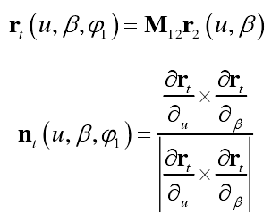
Because the processing capacity of the big wheel is much higher than that of the small wheel, only the small wheel is designed and modified. According to the principle of gear generating motion, the equation of gear rotation angle with high-order transmission error can be used to replace the one without transmission error, that is to say, the formula can be used to obtain the auxiliary tooth surface of the pinion. The transmission error function of the tooth surface is the preset second-order parabola Δ φ 1 (φ 2). Then the normal vector nt and position vector RT of the auxiliary tooth surface ∑ t can be expressed as follows:
Then the three segment composite curve is used to modify the auxiliary tooth surface of the small wheel, and the contact area can be better controlled by using the three section combination curve along the contact track. Here, the three section parabola obtained by crossing two paraboloids is used to modify the contact area and non-contact area of the tooth surface respectively. The parabola modification curve is shown in the figure
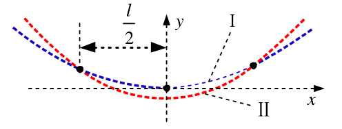
The combined curve segments I and II used in the modification of the auxiliary tooth surface of the pinion are shown in the formula
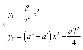
Where a is the preset radius of the long axis of the contact ellipse, δ is the elastic deformation of the contact point, a’l2 / 4 is the vertex spacing of the two second-order curves used, l = 2A, and a ‘is the adjustment parameter of parabola II relative to parabola I. After tooth surface modification, the target tooth surface of the pinion can be obtained.