
CNC machine tools are one of the most widely used manufacturing equipment in the automotive, aerospace, and military fields, playing an important role in industry. Machine tool errors are the main reason for affecting machining accuracy and affecting the overall development of the industry. Therefore, improving the machining accuracy of machine tools while ensuring their processing efficiency is an urgent problem that needs to be solved.
The machining accuracy of machine tools has always been the focus of scholars at home and abroad. For machine tool error models, modeling methods such as multi-body system theory, vector method, and homogeneous coordinate transformation have been proposed. Tian Fengzhen et al. utilized the theory of multibody systems to design corresponding motion chains for machine tool machining parts and analyzed their machining errors; Fu Guoqiang et al. established a contribution value model for geometric errors of motion axes based on exponential product theory and coordinate system differential motion theory, and proposed a sensitivity analysis method for geometric errors of motion axes; Yang Bin proposed a method for measuring dynamic machining errors of CNC machine tools using built-in sensor information and the kinematic model of CNC machine tools; Shi Yan et al. optimized the key parameters in the PID controller to compensate for the motion error of multi axis linkage CNC machine tools, and verified that the proposed method has good adaptability. To improve the machining accuracy of machine tools, it is necessary to control their machining errors, and most people consider error compensation technology as the main way to improve the accuracy of CNC machine tools.
ZHY Gear conducted research on the machining errors of internal helical gears during grinding. Using a multi-body system and the principle of homogeneous coordinate transformation, a geometric error model of the machine tool relative to the workpiece was established. Through online monitoring of the machining process, data collection and analysis were conducted to compensate for the reverse error. This plays an important role in improving the machining accuracy of machine tools and is of great significance for the development of precision parts production enterprises.
Due to geometric errors in different directions during the grinding process of CNC machine tools, the accuracy of the machine tool does not meet the technical requirements. In order to improve the machining accuracy of the machine tool, online monitoring of its machining process is carried out. In the machining process of machine tools, feedback components are used for online information transmission, which can achieve real-time monitoring and control of the operating status and motion accuracy of the feed system.
1. Online monitoring and compensation of machining errors
1.1 Online monitoring
The purpose of monitoring is to collect signal data through built-in sensors, and combine data processing techniques and feature extraction methods to convert it into a processable signal. During the collection process, signal data needs to be sampled, encoded, and transmitted in order to be input into the computer system. Information analysis, processing, storage, and display are completed through the computer system, and these operations can provide critical data for real-time monitoring.
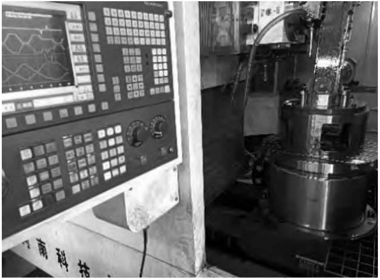
Grind the internal helical gear as shown in Figure 1. During the machining process, the rotation of the C-axis is to ensure that the groove of the machined helical gear is in a predetermined position, the rotation of the A-axis determines the helix angle of the machined inner helical gear, and the movement of the Z-axis is to achieve feed motion in the grinding direction of the helical gear tooth width. During the grinding process of the groove, the X, Y, A, and C axes remain locked.
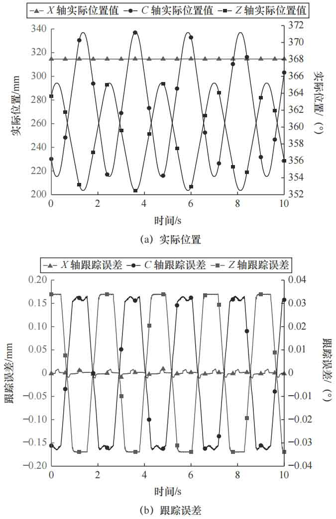
During the testing process, the dynamic position signals of each axis were collected separately, as shown in Figure 2a. Due to the influence of the interaction between the cutting tool and the workpiece, significant changes were detected in the position signals of the X, Z, and C axes, as shown in Figure 2b. The tracking error range of the X axis is about ± 0.01 mm, and the fluctuation amplitude is small; Compared with the X-axis, the Z-axis exhibits significant fluctuations in amplitude, with a tracking error range of approximately ± 0.17 mm; The fluctuation trend of the C-axis position during grinding is similar to that of the Z-axis, and the range of amplitude variation of the C-axis is ± 0.033 °.
1.2 Error compensation
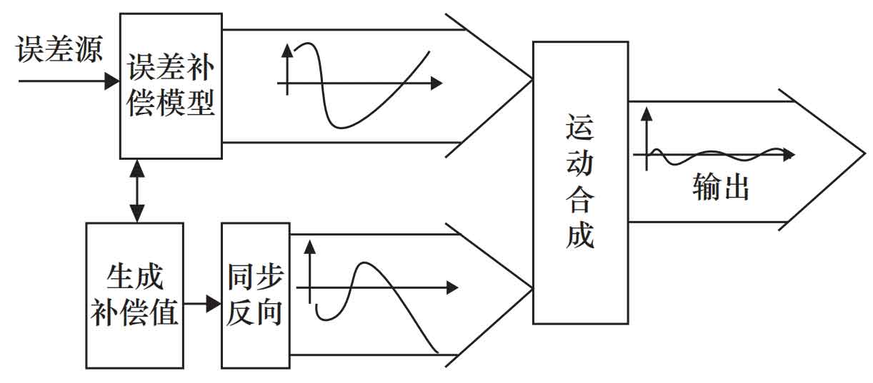
The geometric error compensation of CNC machine tools is divided into hardware compensation and software compensation. Hardware compensation adopts mechanical compensation to improve its machining accuracy. This method is costly, has poor universality, long design cycle time, and is difficult to use CNC methods for feedback control. Therefore, hardware compensation is less commonly used in machine tools; Software compensation is a method of improving the machining accuracy and performance of machine tools by studying the various error sources of machine tools, and combining them with computer software and CNC systems to perform reverse error compensation. The basic principle of software compensation is shown in Figure 3. In the experiment, the list method is used for error compensation of the machine tool. There is no need to change the three-dimensional model of the workpiece and the machining program of the machine tool. Simply input the measured error compensation value into the error compensation table in the Siemens system to achieve error correction.
| Parameters | Numerical value |
| Number of teeth Z | 79 |
| Module mn/mm | 2 |
| Pressure angle an/(°) | 20 |
| Spiral angle β/ (°) | 15 |
| Tooth width b/mm | 45 |
| Displacement coefficient xn | 0 |
Based on online monitoring of machining errors in grinding internal helical gears, the characteristics of axis errors involved in machine tool motion were tested and analyzed, and it was found that the errors in the Z and C axes were relatively large. According to the shape of the error curve, the dynamic operation function is used to real-time compensate the reverse weighted compensation calculation value to the machine tool axis motion, and compensate for its error value.
2. Detection of bevel gear tooth surface error
To verify that the accuracy of the compensated helical gear has been improved, the testing equipment used before and after compensation is Grissom 650GMS. The actual measurement platform is shown in Figure 4.
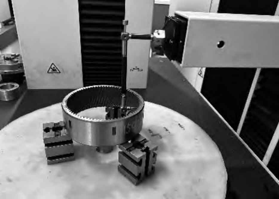
The error of the internal helical gear is evaluated according to the cylindrical gear error detection standard, and actual data is used to represent the influence of machine tool geometric errors on the tooth surface, which are the cumulative total deviation FP of the internal helical gear tooth pitch, the single helical gear tooth pitch deviation fP, and the total deviation F of the tooth profile, respectively α Equal precision standard. Inspect the machining of the internal helical gear before and after compensation, and the inspection reports are shown in Figures 5 and 6.
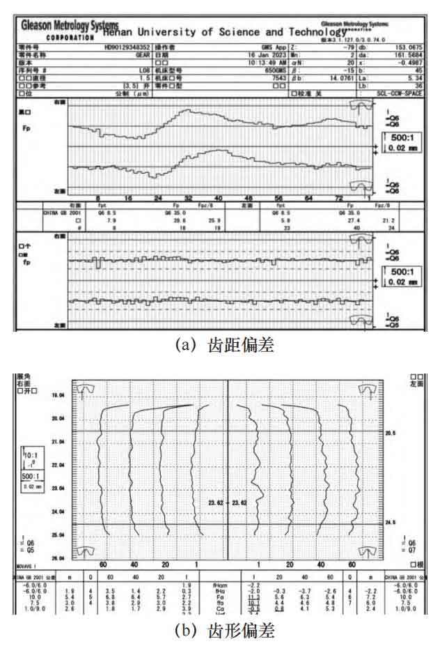
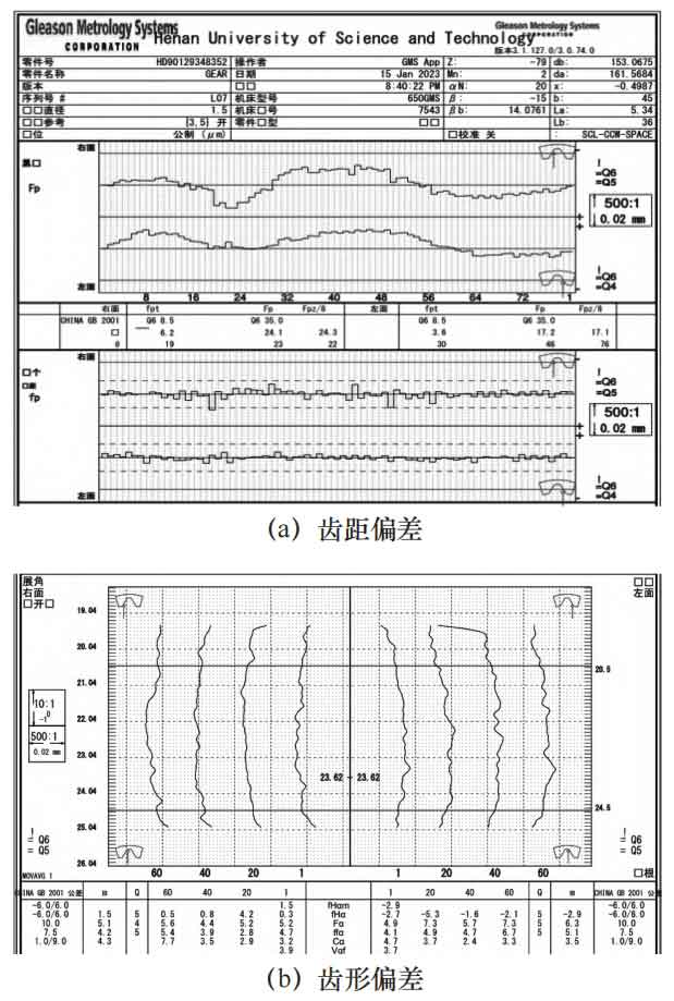
From the table, it can be seen that the machining error of the internal helical gear is significantly reduced after error compensation, indicating a significant improvement in the machining accuracy of the machine tool after compensation.
| Internal helical gear error | Error before compensation/μM | Error after compensation/μM | Accuracy level |
| Accumulated total deviation of right tooth surface FP | 28.8 | 24.1 | Upgrade from level 6 to level 5 |
| Accumulated total deviation of left tooth surface FP | 27.4 | 17.2 | Upgrade from level 6 to level 4 |
| Right tooth surface single tooth pitch deviation fP | 7.9 | 6.2 | Upgrade from level 6 to level 5 |
| Single tooth pitch deviation on the left tooth surface fP | 5.8 | 3.6 | Upgrade from level 5 to level 4 |
| Total tooth profile deviation Fα | 11.3 | 7.3 | Upgrade from level 7 to level 5 |
3. Conclusion
(1) By using the principle of homogeneous coordinate transformation, coordinate transformation is performed on the workpiece bed tool, and a geometric error model of the motion chain is established.
(2) By using built-in sensors to monitor the motion status of each axis of the machine tool during grinding of internal helical gears, it was found that the X-axis error amplitude of the machine tool fluctuated less, while the Z-axis and C-axis error amplitude fluctuated more significantly. Therefore, reverse error compensation was applied to the Z-axis and C-axis of the machine tool.
(3) By using a helical gear detection analyzer, the helical gears before and after compensation were tested. After comparative analysis, it was found that the tooth surface errors of each helical gear after compensation were significantly reduced.
In summary, CNC machine tools have geometric errors in each axis during actual machining. Through the online monitoring system and software compensation of the machine tool, the machining accuracy and surface quality of the workpiece can be improved, which is of great significance for improving the machining accuracy of the machine tool.