
The rotary vector reducer is a pivotal precision transmission component extensively employed in industrial robotics, particularly within robot joint actuators. Its prominence stems from an exceptional combination of high reduction ratio, compact structure, substantial torque capacity, high torsional stiffness, and minimal backlash. As robotic technology advances towards greater dexterity and payload capacity, there is an increasing demand for more efficient and space-saving drive elements. This necessitates the optimization of key reducer parameters to minimize its overall volume or mass while rigorously adhering to all performance and reliability constraints. This article presents a comprehensive methodology for the optimal design of a rotary vector reducer, with the primary objective of minimizing its volume through a systematic formulation of the design problem, application of nonlinear programming techniques, and validation against benchmark data.
Structural Configuration and Operational Principle
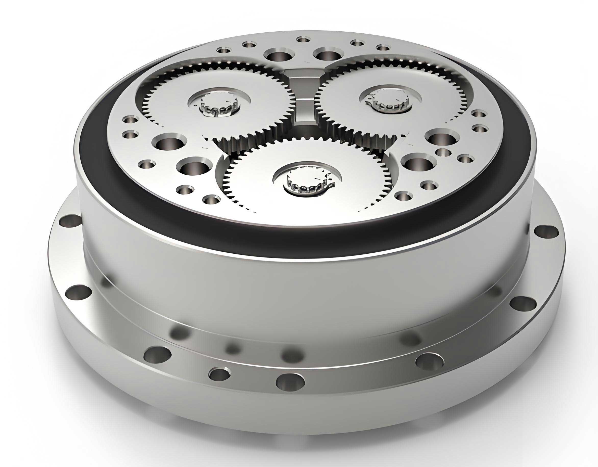
The rotary vector reducer achieves its high performance through a two-stage, coaxial compound planetary transmission system. The kinematic power flow is as follows:
- First Stage – Involute Planetary Gear Train: The input rotation is provided to the sun gear (central gear). This sun gear meshes with multiple involute planet gears (typically two or three), arranged symmetrically. This stage provides the initial speed reduction. The planet gears are mounted on crankshafts.
- Second Stage – Cycloidal Pin-Wheel Planetary Drive: The crankshafts, which rotate with the planet gears, serve as the input to the second stage. Eccentric bearings (cycloidal discs) are mounted on the eccentric portions of these crankshafts. Two cycloidal wheels, with a 180° phase difference, are engaged with a static ring of cylindrical pins (the pin gear). The eccentric motion of the crankshafts forces the cycloidal wheels to undergo a compound motion: a revolution around the central axis (epicyclic motion) and a reverse rotation about their own axes due to the rolling contact with the fixed pins. This reverse rotation is transmitted back to the crankshafts, causing them to precess. This precession is finally output through the planet carrier (output flange).
The total reduction ratio \( i_{RV} \) of the rotary vector reducer is given by the product of the two stages, with the second stage providing the dominant reduction:
$$ i_{RV} = \left(1 + \frac{z_p}{z_c – z_p}\right) \cdot i_1 $$
where \( z_p \) is the number of pin gear teeth, \( z_c \) is the number of cycloidal wheel lobes, and \( i_1 \) is the reduction ratio of the first planetary stage, typically \( i_1 = \frac{z_2}{z_1} \) for a simple sun-planet configuration (where \( z_2 \) is planet gear tooth count and \( z_1 \) is sun gear tooth count, though the specific formula depends on the planetary train configuration). A more precise form commonly used is:
$$ i_{RV} = 1 + \frac{z_p \cdot z_2}{z_1} $$
This highlights the significant multiplication effect of the pin teeth count \( z_p \).
Design Requirements and Material Selection
The optimal design of a rotary vector reducer must satisfy a multifaceted set of performance and durability criteria. These constraints form the boundary conditions for the optimization problem.
- Transmission Efficiency: The overall mechanical efficiency should exceed 85% to ensure energy-effective operation.
- Positioning Accuracy: Backlash must be minimized and controlled within a strict tolerance (e.g., ≤1 arcmin) to guarantee precise robot positioning and path following, especially during reversal motions.
- Service Life: The design must ensure a long operational life, typically defined by bearing L10 life and gear contact fatigue life, often exceeding 10,000 hours.
- Compactness: The primary optimization goal is to minimize the overall volume or mass for a given output torque and speed rating.
- Ratio Distribution: The first-stage reduction ratio should not be too small to fully leverage the high torque capacity and smooth operation of the second-stage cycloidal drive. A common guideline is \( i_1 \geq 1.5 \).
- Ratio Accuracy: The designed total reduction ratio must match the specified nominal ratio within a tight error margin, typically ±1%.
- Geometric Compatibility: The center distance \( a_0 \) of the first-stage gears should be proportional to the pin gear center radius \( r_p \) of the second stage, usually within 50% to 60%, i.e., \( 0.5r_p \leq a_0 \leq 0.6r_p \). This ensures a balanced and compact layout.
Material selection and heat treatment are critical for wear resistance, fatigue strength, and maintaining precision. The table below summarizes typical specifications:
| Component | Material | Heat Treatment | Hardness (HRC) | Precision Grade |
|---|---|---|---|---|
| Sun Gear & Planet Gears | 20Cr / 20CrMnTi | Carburizing and Quenching | 58-62 | ISO 6 |
| Cycloidal Wheel | GCr15 / Cr12MoV | Through-hardening / Vacuum Quenching | 58-62 | ISO 6 |
| Pin Gear (Pins) | GCr15 | Through-hardening | 58-62 | ISO 5 |
| Crankshaft | 42CrMo | Induction Hardening | 50-55 | – |
Formulation of the Optimization Model
The core of designing a compact rotary vector reducer lies in formulating and solving a constrained nonlinear optimization problem.
Objective Function and Design Variables
The total volume of the rotary vector reducer is predominantly dictated by the dimensions of its two main stages. Minimizing the center distance \( a_0 \) of the first-stage planetary gear train directly contributes to a smaller radial envelope and is a effective proxy for minimizing overall volume. Therefore, the objective function is defined as:
$$ \text{Minimize: } f(\mathbf{X}) = a_0 = \frac{m (z_1 + z_2)}{2} $$
where \( \mathbf{X} = [m, z_1, z_2]^T \) is the vector of primary design variables:
- \( m \): Module of the first-stage involute gears (selected from standard series).
- \( z_1 \): Number of teeth on the sun gear.
- \( z_2 \): Number of teeth on each planet gear.
Secondary and dependent variables include the pin tooth count \( z_p \), cycloidal wheel lobe count \( z_c = z_p – 1 \), pin center radius \( r_p \), eccentricity \( a \), and the short width coefficient \( K_1 \).
Constraint Conditions
The design must satisfy a system of inequality constraints derived from mechanical design principles and the specific requirements of the rotary vector reducer.
-
Bending Fatigue Strength of First-Stage Gears:
$$ m \geq \sqrt[3]{\frac{2 K T_1 Y_{Fa} Y_{Sa}}{\phi_d z_1^2 [\sigma_F]}} $$
where:- \( K \): Load factor (incorporating application, dynamic, and load distribution factors).
- \( T_1 \): Input torque on the sun gear, \( T_1 = \frac{9550 \cdot P}{n \cdot i_{RV}} \) (in N·m, with P in kW, n in rpm).
- \( Y_{Fa}, Y_{Sa} \): Tooth form factor and stress correction factor, dependent on \( z_1 \) and profile shift.
- \( \phi_d \): Face width factor, typically \( \phi_d = b / d_1 = 0.3 \sim 0.6 \) for planetary gears.
- \( [\sigma_F] \): Allowable bending stress for the gear material.
-
Contact Fatigue Strength (Pitting Resistance) of First-Stage Gears:
$$ m z_1 \geq 2.32 \sqrt[3]{\frac{K T_1 (i_1 + 1) Z_E^2}{\phi_d i_1^2 [\sigma_H]^2}} $$
where:- \( i_1 \): First-stage ratio (\( z_2 / z_1 \)).
- \( Z_E \): Elastic coefficient (\( \sqrt{\text{MPa}} \)), \( Z_E = 189.9 \) for steel-steel pair.
- \( [\sigma_H] \): Allowable contact stress.
-
Total Reduction Ratio Accuracy:
$$ \left| \frac{i_{RV,calc} – i_{RV,spec}}{i_{RV,spec}} \right| \leq 0.01 $$
where \( i_{RV,calc} = 1 + \frac{z_p z_2}{z_1} \). -
First-Stage Gear Design Constraints:
- No Undercut: \( z_1 \geq z_{min} \) (e.g., \( z_1 \geq 17 \) for standard \( 20^\circ \) pressure angle, no shift).
- Assembly & Symmetry: For a two-planet configuration, \( z_1 \) is usually an even number to satisfy symmetric assembly conditions. Also, \( \frac{z_1 + z_2}{N_p} \) should be an integer for proper planet meshing, where \( N_p \) is the number of planets.
- Ratio Lower Bound: \( i_1 = \frac{z_2}{z_1} \geq 1.5 \).
-
Second-Stage Cycloidal Drive Constraints:
- Geometric Proportionality: \( 0.5 r_p \leq a_0 \leq 0.6 r_p \).
- Pin Gear Center Radius Estimation: \( r_p \approx (0.85 \text{ to } 1.3) \sqrt[3]{T_{out}} \), where \( T_{out} \) is the output torque (\( T_{out} = 9550 \cdot P \cdot \eta / n \)).
- Eccentricity & Short Width Coefficient: The eccentricity \( a \) is related to the pin radius \( r_{rp} \), \( r_p \), and \( K_1 \) by \( a = K_1 r_{rp} \frac{z_c}{z_p} \). \( K_1 \) must be optimized for load distribution and is typically between 0.6 and 0.9.
- Tooth Contact & Strength: Constraints exist to prevent trimming interference and ensure sufficient contact ratio and tooth strength, often involving the design of the cycloidal tooth profile derived from the generating pin circle.
-
Efficiency Constraint: The theoretical efficiency \( \eta \) should be checked. For a rotary vector reducer, it can be estimated by considering the efficiencies of the gear stage \( \eta_g \) and the cycloidal stage \( \eta_c \):
$$ \eta = \eta_g \cdot \eta_c \cdot \eta_b^3 \geq 0.85 $$
where \( \eta_b \) is the efficiency of a single bearing pair.
Design Optimization Example and Computational Implementation
To demonstrate the methodology, we consider the optimal design of a rotary vector reducer with specifications similar to an RV-450E model: Rated Power \( P = 4.28 \text{ kW} \), Output Speed \( n = 5 \text{ rpm} \), and Nominal Reduction Ratio \( i_{RV,spec} = 81 \).
The optimization problem, characterized by mixed-integer variables (discrete \( m \), integer \( z_1, z_2, z_p \)) and nonlinear constraints, is solved computationally. A sequential approach is adopted to manage complexity:
- Stage 1 Optimization: For a trial pin tooth count \( z_p \), solve for \( m, z_1, z_2 \) to minimize \( a_0 \) subject to gear strength and ratio constraints.
- Stage 2 Calculation: Determine \( r_p \), \( a \), and other cycloidal parameters from output torque and geometric constraints.
- Global Search: Iterate over a feasible range of \( z_p \) (e.g., 30 to 50) to find the combination that yields the smallest \( a_0 \) while satisfying \( 0.5r_p \leq a_0 \leq 0.6r_p \) and ratio accuracy.
This process is implemented using MATLAB and its `fmincon` solver for constrained nonlinear optimization. Subroutines are created for gear factor interpolation (\( Y_{Fa}, Y_{Sa} \)) and constraint evaluation. The discrete nature of \( m \) is handled by solving the continuous problem and then selecting the nearest standard, larger module, followed by a final refinement of other variables.
Optimization Results and Comparative Analysis
The following table presents the key parameters obtained from the optimization algorithm and compares them with reference values from literature for a similar rotary vector reducer design.
| Design Parameter | Symbol | Optimization Result | Reference Value |
|---|---|---|---|
| Sun Gear Teeth | \( z_1 \) | 18 | 18 |
| Planet Gear Teeth | \( z_2 \) | 35 | 38 |
| Gear Module (mm) | \( m \) | 3.0 | 3.0 |
| First-Stage Center Distance (mm) | \( a_0 \) | 79.5 | 84.0 |
| Pin Gear Teeth | \( z_p \) | 42 | 38 |
| Cycloidal Wheel Lobes | \( z_c \) | 41 | 37 |
| Pin Center Radius (mm) | \( r_p \) | 154 | 155 |
| Eccentricity (mm) | \( a \) | 3.0 | 3.0 |
| Short Width Coefficient | \( K_1 \) | 0.818 | 0.736 |
| Calculated Total Ratio | \( i_{RV,calc} \) | 82.7 | 81.2 |
| Ratio Error | – | 2.1% | 0.25% |
The results show strong agreement with the reference design, validating the model’s correctness. Crucially, the optimized design achieved a smaller first-stage center distance (79.5 mm vs. 84.0 mm), indicating a more compact radial layout for the rotary vector reducer. The slight deviation in the total ratio (82.7 vs. 81) is within the permissible early-design tolerance and can be fine-tuned by minor adjustments to \( z_p \) or \( z_2 \) in a subsequent iteration. The optimization successfully balances the gear strength constraints, geometric compatibility (\( a_0 / r_p \approx 0.516 \)), and ratio requirements.
Conclusion
This study details a structured methodology for the optimal design of a rotary vector reducer targeting minimum volume. By formulating the center distance of the primary gear stage as the objective function and incorporating a comprehensive set of mechanical and geometric constraints—including bending and contact fatigue strength, ratio accuracy, assembly conditions, and inter-stage proportionality—a solvable nonlinear programming problem is established. The implementation using computational tools like MATLAB demonstrates the feasibility and effectiveness of the approach. The optimized parameters for a sample case yield a design that is functionally equivalent and structurally more compact than a reference design, confirming the value of systematic optimization in advancing the performance-density of critical components like the rotary vector reducer. This framework provides a solid foundation for further refinements, such as multi-objective optimization considering mass, stiffness, and thermal performance, or more detailed modeling of the cycloidal tooth contact dynamics.