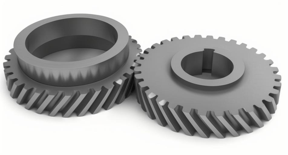
In mechanical transmission systems, helical gears are widely used due to their high load capacity, smooth operation, and reduced noise compared to spur gears. However, the meshing performance of helical gears can be significantly affected by factors such as shaft deformation, which is often overlooked in traditional analyses. This study focuses on optimizing the meshing contact of helical gears in a cutting reducer by considering shaft system influences and applying gear modification techniques. The goal is to improve stress distribution and transmission error, thereby enhancing the overall transmission performance of helical gears.
The helical gear pair under investigation consists of an active gear and a passive gear with specific parameters. The basic parameters are summarized in Table 1 to provide a clear overview. These parameters are essential for calculating the load capacity and performing simulation analyses.
| Parameter | Active Gear | Passive Gear |
|---|---|---|
| Number of Teeth (z) | 20 | 32 |
| Module (mm) | 6 | |
| Helix Angle (°) | 10 | |
| Pressure Angle (°) | 20 | |
| Face Width (mm) | 75 | |
| Profile Shift Coefficient | 0.5593 | 0.5834 |
| Quality Grade | 6 (ISO 1328) | |
To assess the load capacity of the helical gears, the contact stress is calculated using standardized formulas. The nominal contact stress \(\sigma_{H0}\) is determined by the following equation:
$$ \sigma_{H0} = Z_H Z_E Z_\varepsilon Z_\beta \sqrt{\frac{F_t}{d_1 b} \cdot \frac{u+1}{u}} $$
where \(Z_H\) is the zone factor, \(Z_E\) is the elasticity factor, \(Z_\varepsilon\) is the contact ratio factor, \(Z_\beta\) is the helix angle factor, \(F_t\) is the nominal tangential force, \(d_1\) is the reference diameter of the pinion, \(b\) is the face width, and \(u\) is the gear ratio. For this helical gear pair, the calculated nominal contact stress is 966.164 MPa. The actual contact stress \(\sigma_H\) is then derived as:
$$ \sigma_H = Z_B Z_D \sigma_{H0} \sqrt{K_A K_V K_{H\beta} K_{H\alpha}} $$
Here, \(K_A\) is the application factor, \(K_V\) is the dynamic factor, \(K_{H\beta}\) is the face load factor for contact stress, \(K_{H\alpha}\) is the transverse load factor for contact stress, and \(Z_B\), \(Z_D\) are the single pair tooth contact factors. After computation, the contact stresses for the active and passive helical gears are 1,175.01 MPa and 1,140.79 MPa, respectively. The allowable contact stresses for the materials are 1,455 MPa and 1,476 MPa, resulting in safety factors of 1.25 and 1.30, indicating sufficient design margins.

Next, simulation analyses were conducted to evaluate the meshing behavior of the helical gears. First, the gear pair was simulated without considering the shaft system. The transmission error curve and stress distribution on the tooth surfaces were obtained. The transmission error ranged from -69 μm to -43 μm, and the maximum contact stress was 1,173 MPa. The stress distribution was uniform across the tooth surfaces, as expected for an idealized case. However, when the shaft system was included in the simulation, significant changes were observed. The transmission error range expanded to [-74, -49] μm, and the stress distribution showed severe bias, indicating that shaft deformations adversely affect the meshing of helical gears. This highlights the importance of considering shaft influences in the design process.
To optimize the meshing contact, gear modification techniques were applied. Profile modification and lead crowning were employed to mitigate the effects of elastic deformation and manufacturing errors. For profile modification, both profile relief and profile crowning were considered. The profile relief amount \(\Delta\) was set between 0.025 mm and 0.040 mm, with a tip relief length \(h\) of 2.1–2.7 mm and a radius \(R\) of 0.75 mm. Profile crowning amounts of 10 μm, 20 μm, 30 μm, 40 μm, and 50 μm were analyzed. As the crowning amount increased, stress concentration at the tooth ends decreased, while the maximum contact stress gradually increased. A crowning amount of 30 μm was selected as optimal, as it balanced stress reduction and contact performance.
For lead crowning, the modification amount was determined based on elastic deformation, with recommended values ranging from 13 μm to 35 μm. Different amounts—13 μm, 18 μm, 23 μm, 28 μm, 33 μm, and 35 μm—were simulated to assess their impact on contact stress distribution. The results, summarized in Table 2, show that as the lead crowning amount increases, the contact pattern shifts toward the center of the tooth surface, and the stress distribution improves. A lead crowning amount of 28 μm was chosen for further analysis, as it provided the best compromise between stress distribution and contact performance.
| Lead Crowning Amount (μm) | Maximum Contact Stress (MPa) | Contact Pattern Description |
|---|---|---|
| 13 | 1,158 | Wide distribution with edge bias |
| 18 | 1,165 | Moderate centralization |
| 23 | 1,172 | Improved centralization |
| 28 | 1,180 | Well-centered pattern |
| 33 | 1,190 | Slight stress increase |
| 35 | 1,195 | Centralized but higher stress |
After applying the selected modifications, the transmission error and stress distribution were re-evaluated. The transmission error range was reduced to [-75, -61] μm, representing a 37.5% decrease in fluctuation compared to the unmodified case with shaft influence. The maximum contact stress increased to 1,243 MPa, but the contact pattern became more uniform, significantly improving the meshing performance of the helical gears. This demonstrates that proper gear modification can effectively counteract the negative effects of shaft deformation.
In conclusion, this study underscores the critical role of shaft system considerations in the design of helical gears for cutting reducers. Through systematic profile and lead modifications, the meshing contact of helical gears was optimized, resulting in reduced transmission error and improved stress distribution. The methodologies presented here can be extended to other applications involving helical gears to enhance reliability and performance. Future work could explore dynamic analyses or material optimizations to further advance the design of helical gear systems.
