
According to the influence law of the impression shape on the internal excitation of the spiral bevel gear, a pair of spiral bevel gear pairs with better dynamic meshing transmission performance are designed, so that the meshing impression is 12% smaller, the meshing trace is inclined by 50 °, the impression length coefficient is 0.3, and the relative angular velocity of motion is 0.0008. The method described in Chapter 3 is applied to the tooth cutting adjustment calculation and contact characteristic control experiment of the spiral bevel gear. Firstly, the position control experiment of the contact reference point is carried out, and the contact reference point of the concave convex two sides of the big wheel is selected at the smaller end of the middle of the tooth width by 12%. Figure 1 shows the contact area of the convex and concave sides of the large wheel calculated after the position control of the contact reference point. It can be seen that the reference points in the contact area reach the specified position, but the transmission error curve is not continuous at this time. This situation is mainly due to the large transmission ratio of spiral bevel gear pair, the large wheel adopts large positive displacement, and the tooth top height is small. The contact reference point can be moved to the tooth root direction by 20% of the full tooth height, and the transmission error curve becomes continuous and symmetrical, as shown in Figure 2. Of course, this situation can also be solved by reducing the number of teeth of the small wheel.

Then the experiment of contact zone shape control is carried out. The length coefficient of the contact area on both sides of the convex and concave is set to be 0.3, the diagonal angle of the contact area is 50 degrees, and the transmission error amplitude of spiral bevel gear is 15 angle seconds. The optimization method is used to solve the control variables of each contact characteristic. It can be seen that the shape parameters of the contact area are basically consistent with the set parameters, and there is only a slight difference in the amplitude of the transmission error of spiral bevel gear. The gear cutting adjustment parameters of the corresponding large and small wheels.

Then, the five tooth contact finite element model of the spiral bevel gear pair is constructed to analyze its internal excitation, and its internal excitation curve is shown as the red line in Figure 3.
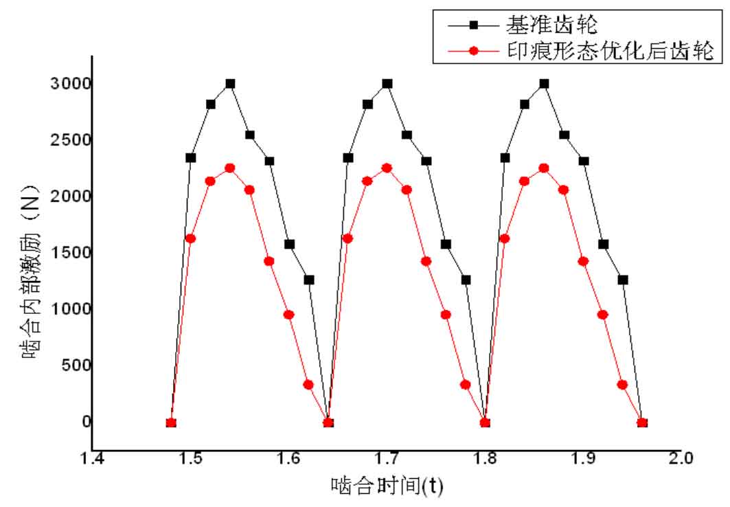
Compared with the internal excitation curve of the benchmark spiral bevel gear with good transmission performance, it can be seen that the internal excitation curve of the optimized spiral bevel gear pair is smooth, and its excitation amplitude decreases by about 30%. Fourier transform the two groups of curves to obtain the excitation amplitude under different meshing orders. As shown in Figure 4, it can be seen that the excitation amplitude under the first-order meshing frequency of the optimized spiral bevel gear decreases by 9.6%, and the excitation amplitude decreases more obviously with the increase of meshing order.
